Ambika: Build your own polysynth
In 2015 I made a decision to perform live again. I’d devoted the previous decade to what I called a “live/DJ set” where I would use CDJ and/or Traktor to mix music, stems, and sound together and use my voice over the top to sing, chant, incite, and love the audience. It was wonderfully fun, connected deeply with many people and I grew a lot as an artist as the result of portability, and ease of integration, but by early 2015 I was done with this and looking for inspired performances, real time interaction, and something much more interesting and unique than this sort of pre prepared, and easily overlooked experience. So I began to look around and see what was available to electronic musicians in terms of modern equipment. Not at all interested in the past, meaning I didn’t want to lug vintage gear around with me, nor could I afford to buy any of it, so the question was: What’s new, useful and interesting?
Eurorack modular synthesizers instantly caught my attention, and the monosynth was assembled, Roland released the TR-8 and so the drum machine was acquired, various wonderful 303 like boxes were a pleasure to explore, and the Octatrack is such a wonderful sampler/sequencer that sampling was organized, but what about the polysynth? I looked around for a multitimbral polyphonic sampler which might be able to sort of operate as a polysynth for live performances, but the beasts are extinct. It’s a shame, but it’s either vintage or bust when it comes to polyphonic sampling. So I explored some of the recent past: Access Virus A and the TI Snow were two things I tried out, and really loved, but somehow they each had their shortcomings. In truth I could have probably used anything, but I wanted to use new gear. I really wanted my tour to be all about available, accessible, and new devices which anyone could get their hands on. So I kept looking…
Searching for “modern desktop polysynth” in early 2015 was about as distressing as searching for “modern desktop polyphonic sampler” is now (and was then) but we’ve actually come a long way since then (and I’ll get to that) but at the time everything was $2,800 or more, and a beast. Huge and unwieldy, well out of reach. So I dug a little deeper until I discovered this video:
If for whatever reason the video doesn’t actually load and the above area is blank, just reload and it’ll show up
Just the first few seconds of the video captivated me. “What the hell is Ambika?” and “who the crap are Mutable Instruments?” followed immediately by a search and a little reading and I found out that Mutable Intruments are a company who make really cool synthesizers called things like Ambika, Shruthi, and Anushri and you can build them yourself!
I got very excited and reached out. Sadly it turned out that Olivier Gillet is a degree holding enthusiast from France and he’s responsible for Mutable Instruments, but despite his amazing work and exploration I was late to the party. At the time I reached out to him for things to build my own he had already made the decision to move on, and stop making these wonderful little DIY/Open Source boxes and move on to become one of the most inspired Eurorack Modular developers to date. He was very kind to reply to my novice communications, and Olivier pointed me toward Andre at TubeOhm and Adam at Laurentide Synthworks because these people had undertaken the continuation of the Ambika and other projects and were producing kits, PCB’s and more. At the time I was sure that there was no hope of my ever really firing up the soldering iron and doing much more than burning my name into the table with it. I had taken a lot things apart, and not all of them ever got put back together. Soldering wasn’t something I thought I would even really like, let alone be good at. So my questions to these good people were geared more toward “Can you build this for me please?” rather than better questions like “How hard is this to learn to do?” and “If I want to eventually be able to build a polysynth, where should I begin?”
The response was kind, and patient, but also cost prohibitive. By the time a capable tech built me something, the cost was getting up toward the price of buying something which was already out of my reach. So I was at a crossroads – Do I wait, save up, and continue to work as I have been working until I’ve got the resources to buy better devices? Or do I find another way? Being me, I decided to find another way. And lucky for me Roland announced their lovely little boutique synth line right about that time. So instead of going further, I purchases all three of the initial Roland Boutique synths – JP-08, JU-06, and JX-03 and toured my head off.
What I learned touring is that having knobs and sliders is amazing (read that as something more like Oh my fucking god, why the hell did I ever touch a computer to replace these wonderful things!!!? and you’re starting to get close to just how amazing it was.) But I really only loved the JU-06. The JP08 could have easily been a second Juno, and really, the same it true for the JX. They aren’t unique enough, nor different enough, nor do they actually sound wonderful enough to be my entire synth engine for live performance. I found myself messing with them live, sub mixing them into their own mixer, adding a lot of effects, and struggling with how small they are in dark clubs, and small areas. I love them, don’t get me wrong, but I would have been happy with one of them, and something more complex as a layer, or even a stacked relationship to produce a wider, deeper, and more flexible result in performance. So I went back to looking for a polyphonic multitimbral sampler…
Meanwhile I found myself picking up a soldering iron after all. I began to repair things, and tried to build my own Eurorack module. I started to get some confidence, and assemble some tools. After building a multiple, a couple of filters, my own oscilloscope, an envelope, a sequencer, and helping to repair a handful of things I returned to the idea of building the Ambika. Trouble is that now in addition to Mutable Instruments no longer producing the needed kits, now Laurentide Synthworks is rumored to be about to retire too! So I went searching at places like Modular Addict and began trying to assemble an Ambika Kit with all six voice cards and the mother board, as well as pre programmed MCU chips. I’d recently attempted to program a couple of different chips using a pickit programmer and it was a nightmare for me. As a mac user, having bought the pickit programmer on eBay (turned out to be a clone) there was no support, and in the end had to revive Martha’s old VAIO PC and do it that way, but the thought of going through all that again with a new and foreign platform on an antique PC wasn’t looking good.
So I finally reached out again to Andre at TubeOhm. We discussed the kits, and my various options:
The Synth consists of the Mother Board – all Ambika’s need this in order to work at all – and then a choice of voice/filter cards:
1. SMR4/SMR4 Plus – the LPF Roland style voice card.
2. P4 – Punchy, more of a Waldorf sounding voice card.
3. SVF – Multi mode filter LP, HP, BP
4. Ladder – LP based on the Moog transistor ladder filter
5. Polivoks – A voice card based on the Russian Polivoks synth filter
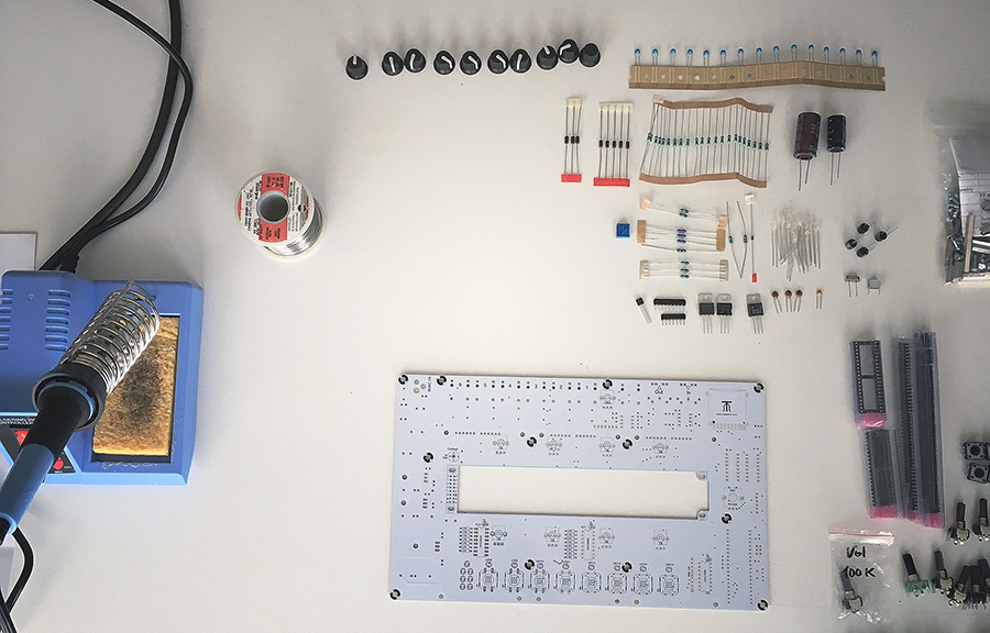
I wanted to go slowly, and build thoughtfully. That’s not as easy as it sounds… my experience tells me that I want my synthesizer and I want it right now! So having a box of little tiny parts, and an envelope with PCB’s in it, and another box with jacks and connectors still in the post from China is a little bit of a patience tester. It’s hard to wait. Once it’s all on the table in front of me it’s even harder to go slowly.
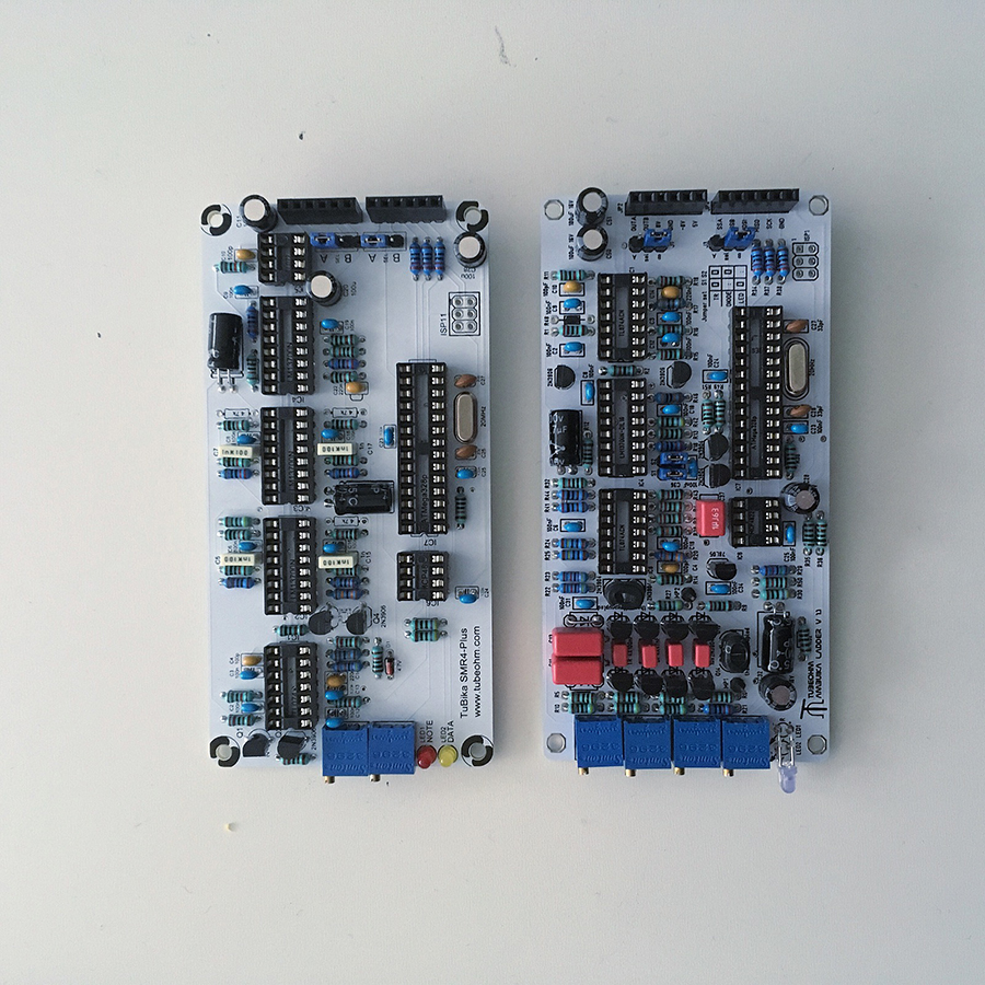
I decided on a Mother Board, and two SMR4 Plus voice cards. Before they arrived the Euro dipped sharply against the dollar and I called up and ordered two more (this time a third SMR4 Plus and a Ladder voice card.) The Euro went right back up again, and so I really wish I’d gotten the rest of the six cards I intend to buy, but again, I wanted to go slowly and take it a step at a time.
The parts list is not so long, and these come in a couple of flavors:
1. Order a kit, and receive all the parts in a couple of bags. This is easier, but a little more expensive. But you know that what’s in front of you is correct, and can begin as soon as your soldering iron is heated up.
2. Source your own parts yourself. There are various BOM (bill of materials) out there for the Ambika, and you can follow them and source your own parts from popular places like Tayda and Mouser Electronics. This is an interesting way to go, because it saves you a little money, but also allows us to get more involved in the individual components, their source, and to make choices. This is a worthy education to have, but if it’s your first build ever I suggest getting the kit (and maybe starting with a multiples or something very simple just to get started.)
A Word About Soldering
Lots of people have lots of ideas about soldering. There are many guides to how to approach this, and acquire the skill. I suggest spending some time on the AI Synthesis web site and read up on some of their suggestions. Lovely people, with great, easy to understand perspective. They make great modules too.
In terms of the actual soldering, Adafruit have a superb guide to soldering here Where they visually demonstrate the process, and show good examples, and bad ones. Personally I began, as most people do, with a bad soldering iron, and bad solder, and I used way too much of it. My skills are those of a beginner, and while with good tools (lead solder, a better soldering iron, a magnification visor, better snippers and good tweezers) I have been able to move from much too much, to far to little, to some steady handed and well placed soldering. I have even tried my hand at some SMD (surface mount component) soldering, and while magnification is essential in this process, it isn’t half as bad as it seemed at the start. It actually turned out to be kind of thrilling.
A Word About Troubleshooting
The main thing is to appraise your skill level honestly, take your time, and learn. I find being in over my head a little bit is a good place to be, as it turns out that building is the quick and easy part. The real work of constructing electronics is in troubleshooting and correcting once the device is assembled. De soldering, re flowing, cleaning, and troubleshooting have been where the real lessons are learned.
For example, it’s not enough to solder something into place if the connection you’ve made doesn’t work. It’s normal response in this buy and dispose it world of ours to think that the part was wrong (and you’re an idiot) or that the design doesn’t work (and they’re an idiot) but that’s not necessarily the case. While soldering is basically a durable method of creating connection between components so that voltage may pass through, sometimes we make mistakes. Telling the difference between resistors is an art in and of itself, inverting a capacitor is a common mistake – is the long leg positive or negative? – and sometimes things are just wonkey. So the art and skill of patiently going back over one’s work to look for light solder, solder blobs, bridged solders (where two things got accidentally connected which shouldn’t be connected) and trouble shooting to be sure that the right things are in the right place and the right way around is a very important skill, not just in know how, but also in terms of patience and stamina.
My mentor in this area said to me after I had a capacitor blow up in my face, and I was feeling totally defeated “True patience takes time.” At the time it felt ironic and impossible (sort of like the old you need a job to get a job situation) but it’s true. Real patience is earned. Take your time. Learn.
The build wasn’t really all that difficult. I think I was just freaked out because it was my first polysynth project, so I was nervous, and excited. As I said above, the hassles were not in the initial assembly, rather, the challenge of the build was in how I responded to my haste, and error. Troubleshooting, diligence, and thoughtfulness was what it turned out to be all about.
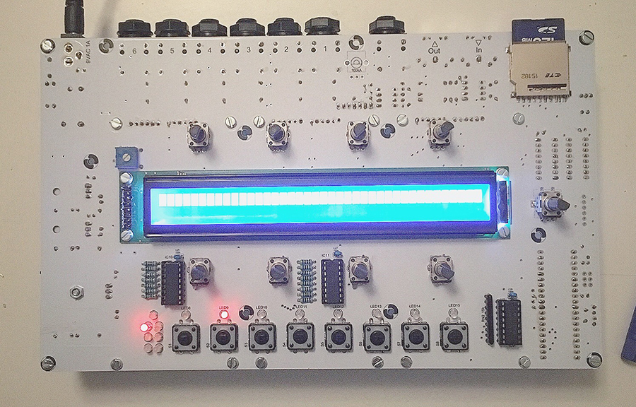
There are really clear, and very thoughtful step by step instructions on both the TubeOhm site, as well as still in place at the Mutable Instruments site. I followed the instructions, and soldered my parts and attached the IC sockets and then I realized I’d really messed up. I soldered the LCD display onto the wrong side of the motherboard. Crap! I thoughtfully and very slowly heated up the pins and slipped them out and then gently removed the LCD from the PCB. In the process, careful as I was, I not only compromised the mother board, but I also pulled up traces and ruined the LCD. Dang! I communicated with a friend who’s way better at all this than I am and we took a look, but it was true, I’d bungled it.
That didn’t stop me. I ordered a replacement LCD off eBay for less than half of what the first one cost, and continued to build the voice cards, and troubleshoot the synth blind. It sounds wonderful, and it works beautifully. I love it so much, but I can’t see what I’m doing at all. I call it the Blindika!
UPDATE
The two additional voice cards arrived today and as I expected it was impossible to set them aside and wait for the arrival of the LCD. So I opened the box and laid out my parts, tested the voltages of the resistors, and fired up the soldering iron.
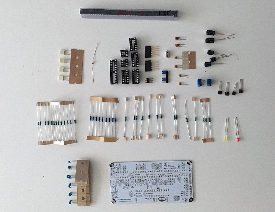
The two cards which arrived were an additional SMR4 Plus card (to make three) and a Transistor Ladder Filter card. I was thinking that I might want to have three of the SMR4 cards to make pads and general polysynth cutie, but it would be fun to have a ladder filter and perhaps eventually a polivoks voice card for making mono synth sounds along side the other voices for a more dynamic and interesting set of sounds. I came to regret this decision after I’d built the voice cards and tried them, but I’ll tell you more about that when we get there.
The parts are either included in the kit (if you get yourself a “full kit”) or else you’ve chosen them yourself, or scored them from a pre created cart or BOM document. The electronic components shops we love are pretty cool, they allow users to save and share carts. Some allow you to export your wish lists and carts at files which can be emailed, uploaded, and shared. With one of these files you can simply upload it to a site like Mouser and it will populate a cart for you. It’s not always a great idea to just trust that what people think you need it right and buy these parts without going over them first. It can be really tedious to look at various types of capacitors and resistors, but going over the parts list can both allow you to become more comfortable with the names and specifications of electronic compontents, but also you might find some weird errors, or strange (expensive) choices which you can curate to suit your needs better.
In my kit the resistors were each separated into specific types, but they were not marked. I had to pull out my mult meter and check the values of each group and make a little note on the paper holding them together so I would know where to put what. It was helpful to measure, mark, and set my parts out in an organized manner so that I could easily locate them during the build. It’s best practice to start with the smallest parts, and build up. So little things go in first, and we work our way up to the big stuff.
I’ve learned about things that seem to take more than two hands. For example an IC slot has a lot of little pins and it can be a challenge to hold it into the holes, and flip the circuit board over and set it down while keeping the component in place and ready to be soldered. The tip I have to offer is that you solder just one of the pins, and then hold the board in a way which allows you to heat it and adjust it so that the whole piece is flat and in place as it should be. Then the component is fitted correctly and firmly in place, and it’s time to go over the rest of the pins until it’s done.
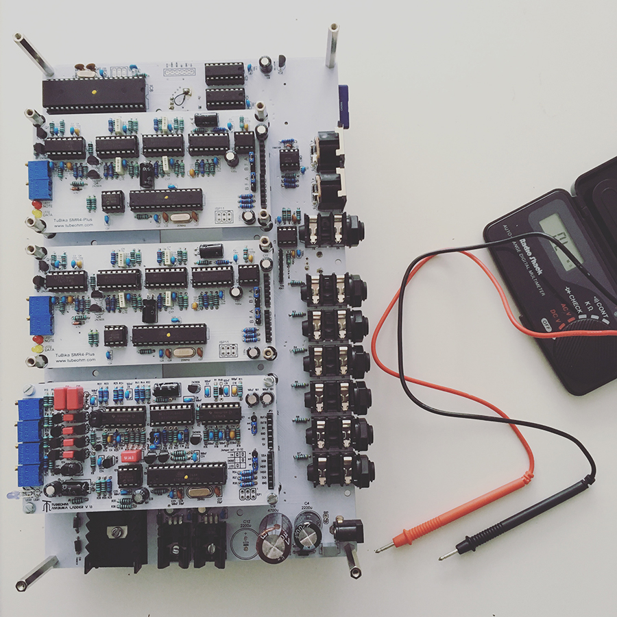
Once I assembled the voice cards I put them into the mother board, and tested the voltages. In the build document there are various tests to perform in order to make sure you’ve got everything just right. Another tip I’ve learned is that one of the most important parts of building things is not so much about doing it all perfectly the first time, but rather getting our heads together about possible mistakes – how to spot them, and what to do about them.
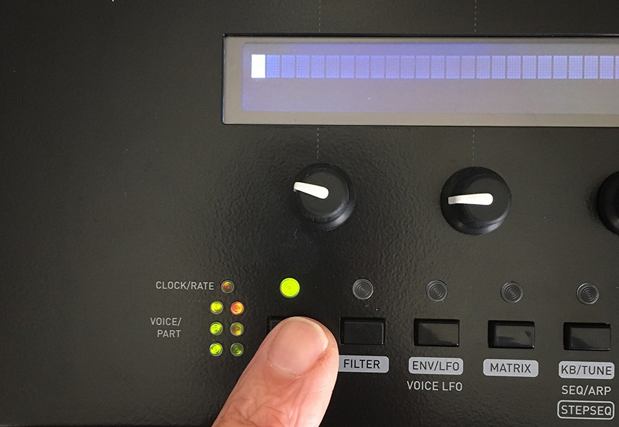
For example, once I assembled the transistor ladder voice card and plugged it in I was very surprised to hear a wildly distorted and unpleasant sound. I assumed it was because I hadn’t adjusted it yet, so I carefully followed the calibration instructions in the build document, and got even more confused. So I wrote to the people who made the voice card and asked their advice – including the picture above. They wrote back reaffirming the build documents calibration instructions, and also suggested that maybe I hadn’t put all the right things in all the right places. With this information I took a closer look, and discovered that indeed I had misplaced two of the transistors. I had an 06 in an 04 slot, and an 04 in an 06 slot. It was easy enough to heat and slip the wrong ones out and after removing the extra solder, I inserted the right ones in the right places. I plugged the card back in and it sounds wonderful.
It turns out that after building the basic synth, and adding the voice cards that I really love this synthesizer. It’s a beautiful thing, and I built it. Exciting as that is I began to wonder what I was thinking when I wanted anything other than a six voice polysynth. At this writing I have changed my mind and would like to add three more of the same cards to inevitably accomplish a full on six voice polyphonic synthesizer with all the same capabilities on all the voices. As much as I love a variety of sounds, I think that it’s possibly asking too much of a synth that’s this intimate to be the bass, and the percussion and the pad… it might be a better idea to use all the faculties of this device to produce layer upon layer of it’s lush beauty… and this might just take all six voices.
Here’s how the blindika sounds with just three of these SMR4 Plus voice cards installed
Update: The adventure of LCD Replacement
When I removed the original LCD I was as careful as I could possibly be. My soldering iron is at 450 degrees F and i very methodically removed each pin from the header, from the bottom side, and slipped them out one by one, and then applied a little heat with a heat gun, and gently, gently waited for the solder to flow so I could remove the circuit board from the circuitboard. Seems like good practice, but of course I totally hosed it. I ruined the original (very pretty) LCD display unit by pulling up traces which simply couldn’t be jumpered. The Mother board of the Ambika was still salvageable, but it needed a little attention too. Solder sucking is a violent activity, an I lost three pads in the adventure.
Approaching the LCD installation for the second time I took care to first clean everything. Acetone is a great way to clean off rosin and other gunk, isopropyl alcohol is a great way to clean everything off. Once clean the task was to repair what was broken. So an x-acto knife was used to carefully etch away at the traces where the pads had come off, until copper was exposed, and then little teeny tiny bus wire was used to connect to the freshly exposed copper.
Soldering this isn’t always easy. You need light, a magnification visor, and a great pair of tweezers. Tin the tip of your iron, and holding it to the wire, tin the bus wire a little. Then tin the copper a little bit too. It does’t take much. Then hold all the parts together in place and apply the iron again. This simply connection with heat should bring everything together. Just breathe, and relax, and laugh with the process if you get shaky or things are super close and then you have to start all over again… it’s all normal, and all a part of the adventure.
So once the three missing pads were jumpered to the copper traces it was time to apply the bus header.
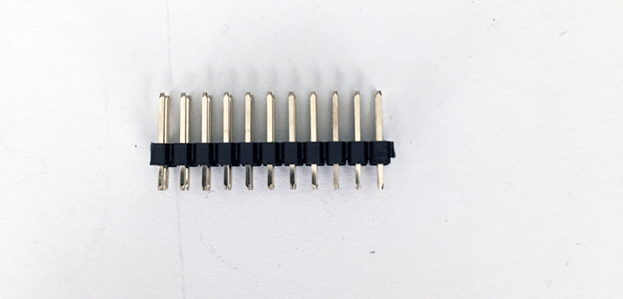
* Pay attention to this, because it caused a serious problem which I’ll share the solution for later.
The build instructions for this, at my second reading, were confusing. They aren’t confusing on purpose, but rather, there are many different types of 5v LCD display units, and they are different and require different treatments depending on which one you choose.
The nice one I ruined went in the top of the PCB, and was enclosed so that it did not want screws under it, rather just connect it, screw in the screws to the bolts on the under side of the PCB, and solder the header. Simple. So simple I totally messed it up.
The Optrex version which is very nice can be mounted underneath the circuit board, and is connected differently.
The unbranded LCD replacement I got from China for $6 needed plastic washers to lift it up from the circuit board, and then some more fun: It was 3.3V and not 5V as advertised.
So I waited 5 weeks, and at last I’m ready to install my LCD and be all done, but I can’t because of some oversight. Argh! But instead of doing anything rash, I wrote to the people at the company I purchased it from and said something like “Hey! This isn’t a 5v LCD, you sent me a 3.3V LCD display. I would like you to ship me the correct voltage device ASAP please.”
They responded immediately and said A) Yes they would send me another display, and it would take another 5 weeks to arrive. But that B) I could adjust this display to operate at 5V… Interesting.
Here’s what I did:
R11 was removed. R12 and R13 resistors were replaced with 51R SDM components and it was fun. Turns out I actually get a little thrill from soldering SMD components. They’re no larger than a grain of sand, and when they set into place, it’s a delight. Kind of unbelievable.
So with the LCD unit adjusted it was time to install it at last.
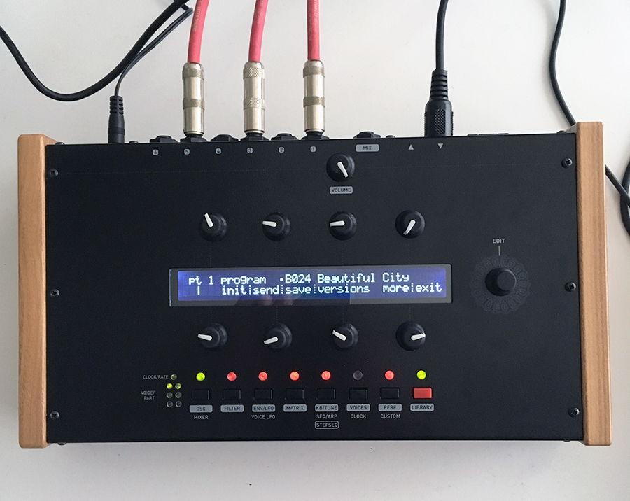
Simple: Fit the LCD onto the header, screw in the screws with washers below, nuts on the bottom and then solder the 16 pin header. It seemed to get well, looked very clean, and upon power up the LCD worked!
Seemed like a great success.
Adventures Continue
It was a pleasure to spend time with the Ambika with a screen. It was like a completely different synth when you know what you’re doing. There was a little part of me what missed the blindness of working by feel and sound only, and maybe I jinxed myself, but after a couple hours of play and exploration something started to go wrong.
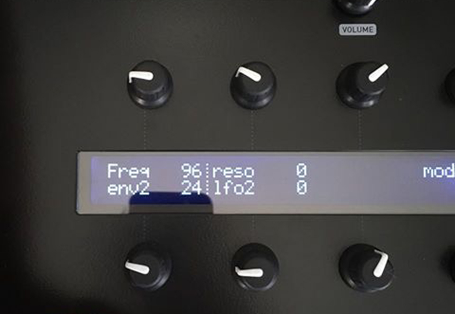
Working LCD Screen
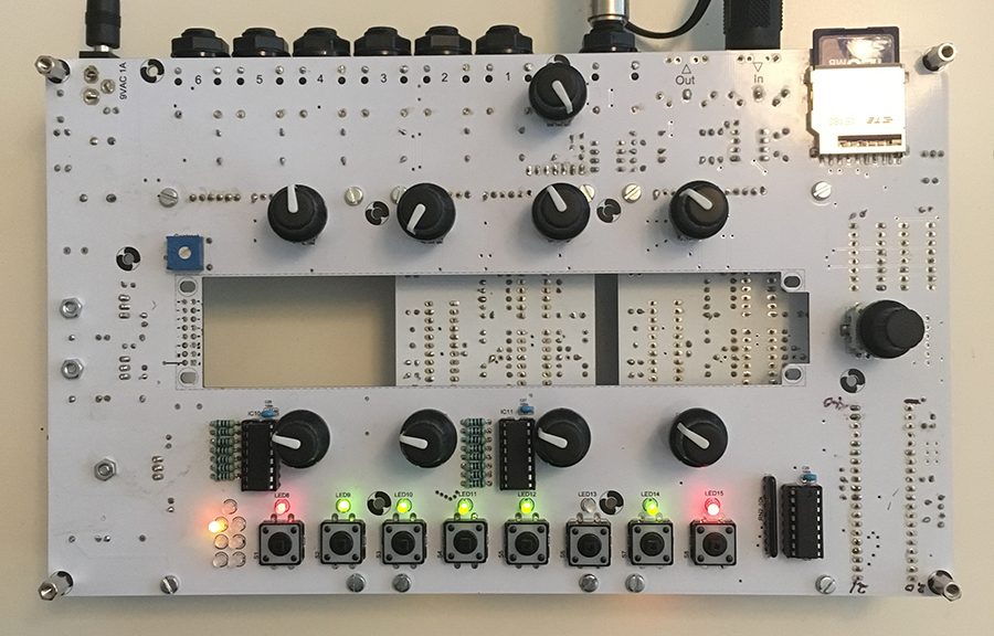
Not Working LCD Screen
It turned out that after an hour or so the screen would default to a single blinking cursor. Restarting made things worse. The only fix seemed to be to switch the synth off, and let it sit for about 10-15 minutes and then I could repeat the cycle all over again – an hour or so of exploration, and then a single blinking cursor. I found this so distracting and discouraging that I began to search the web, write to the manufacturer, reach out to others, and read up on 3.3 to 5v conversions and see what in the world could be wrong.
I meditated on the pre LCD resistor value – this is a confusing part of building the Ambika where you are to choose a resistor value for the motherboard which will create a buffer for your LCD display. In many cases a jumper wire will be sufficient, in others a 100R resistor will save your Optrex LCD from burning out upon power up, and the resistor values in between will adjust the brightness of your display. This made sense to me, and I felt that perhaps it was either getting too much resistance from my 47R resistor in place, or perhaps not enough. I folded this over and over in my mind until I saw that brightness resistance really couldn’t be the culprit here.
Meanwhile the problem appeared to be degrading. The time of active LCD screen was growing shorter and shorter until eventually it wouldn’t let me see at all. It was back to crappy and a single blinking cursor all the time. I kind of resigned myself to the idea that this LCD was a bad decision, and I would probably need to remove it, risking screwing up the mother board even more, and install the replacement which has still not arrived from China. But turning the board over and over in my hands, looking closely, and considering voltage, ground, resistance, intermittent degrading connection it seemed like the problem might actually be simply the connection on the header (see the picture above.)
So I gently moved things around a little bit, and I watched as the screen went dark, lit up, grayed out, and turned back on. Was it possible that the solder connections were simply friction here and there was no actual solder on the correct side of the board? I turned the board around again, and saw my soldering on the top side, and the plastic pin header holder on the bottom side. I looked, and looked and it seemed that I had a good connection on one side, and literally no connection on the other side. Heavy. We needed a connection on both sides. So At the suggestion of the lovely Kevin Siegenthaler I wiggled the black plastic connecter up and off the pins until it was gone and the pins were totally exposed, and soldered the other side as well.
A flip of the switch and the LCD roared back to life. Perfect in every way.
Hours later, there is no intermittent behavior, and all is well. At last the Blindika, and the half-Blindika can see, and are functioning perfectly.
NEXT
The last steps in this process is to decide about the voice cards and choose how I’d like to use this synthesizer, build the cards I choose and install them.
I’m debating:
a) All the same cards for a 6 voice SMR4 Plus polysynth
b) Three SMR4 Plus and 3 SVF Voice cards for 3 lowpass and 3 multi mode voices to create layers
c) Four SMR4 Plus for a 4 voice Polysynth and then keep the Ladder filter card, and add a polivoks, and a SVF card for individual voices, and alternate textures and layers in more complex sounds.
At the moment I am leaning toward options A and B but I’m totally open to dialog about it. Still haven’t decided.
And there is also the question of firmware. There is the original Mutable Instruments firmware, as well as a couple of other versions available p57 and YAM have both released alternates for loading and experimenting. They promise more features as well as more interesting wavetables for improved sound. I’ll install them and review them here for your pleasure.
Until then…
16 Comments
Elaine Marigold Avery and Gabriel Whitten I wrote this up for you… hope it helps you make a choice and encourages you to begin.
oooh! thanks so much!
Thank you so much buddy, I’ll check this out for sure
you can do it, for sure. fwiw first time I opened a Technics I pulled up traces trying to do a repair. It’s often said that making stuff is less about building, but figuring out how to fix the inevitable mistakes.
That’s exactly right. Experience has shown me that it’s all in the troubleshooting and reworking to perfect the connections and refine the voltages.
and dont forget your Vitamin C or orange juice if you feel spacey after a days work.
Engineer! Imagineer!
Funny, when I think about it, the first electronics kit project I helped build came from right near you, Free Radio Berkeley. A 1/2W PLL TX and a 40W amp. Wonder if FRB is still kickin’?
Sunshine Jones, I missed out soooo many adjectives and nouns: Lover, Groooovemeister, DiscoUberKind. (I made the last one up … I’ve no grasp of German, but I meant Super Disco Kid! And if this term means one ounce of sense I’d love you to make it a track title). As ever… Love, Love, LOVE!
Blindika!! great read. : )
Thanks Sunshine. I’m looking forward to reading and learning more in your next installment.
Best wishes from Cambodia.
~Warren
Cool, I love it! I’m getting super exited about the DIY area at NAMM.
Love you Sunshine Jones
Thank you, Sunshine! We’ve been following your posts, catching you live when we can, and loving the synth reports! We are beginning ( or revisiting) modular world. Our table is full of equipment, and rediscovering the love of live electronic music. As always, thanks for the inspiration!
* UPDATE *
I added more about the tools and tips regarding soldering and reworking your project.
No further progress on the device yet, but I added what I hope is more helpful guidance.
* UPDATE 2 *
I made a lot more progress and added the pictures, and a running update of my progress and lessons learned.
LCD is here! So there will be more soon!