Din Sync GILBERT // DIY SH-Style Mono Synth Project
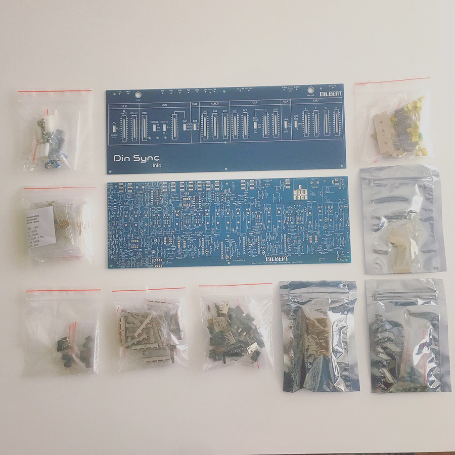
Din Sync’s highly anticipated and absolutely thrilling Gilbert kit has arrived.
This is an analog SH-101/MC-202 synthesizer which was offered (for less than a day) as a complete kit.
I was lucky enough to score one, and it’s arrived.
I’ve rarely been this excited about something.
If you didn’t manage to score one of these kits and you’d like one, Paul says that there should be more of them coming soon.
Get all the lowdown at re-303.com
This is the journal of the build and how it turned out:
FIRST THING’S FIRST – Organize and Read
It’s in my nature to switch on the soldering iron and just start melting metal and putting things together. I have bungled a decent number of things, and it’s become fairly apparent to me that I can convince myself of practically anything. If it “feels right” solder it! seems to be the motto of my unconscious mind. So in an effort to actually grow, and make better use of my time and effort, I sat down and read the build document, and made some notes about anything that was interesting, or looked like it might be challenging for me.
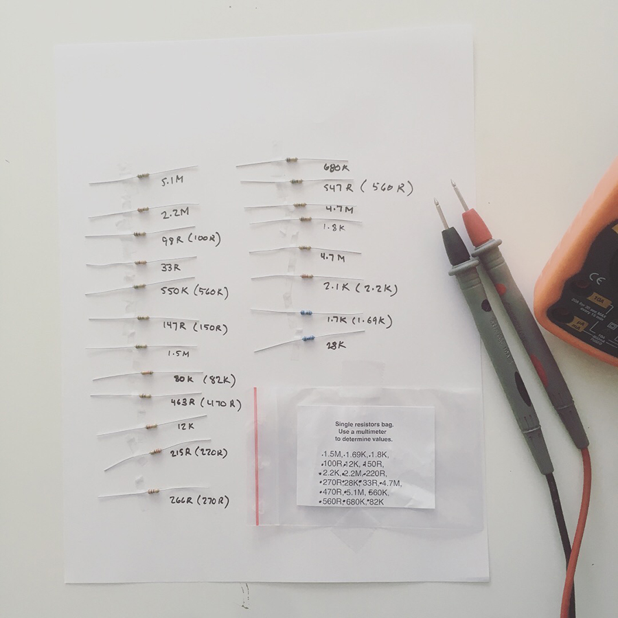
As the result I actually did what the guide suggests: I unpacked the bag of single resistors and taped them to a piece of paper, measured them all and noted their values. I did this as an exercise in following instructions (something that for whatever reason I resist) and also so that I would actually know what part was what when it was time to reach for it. I did it exactly as directed, and I was glad I tok the time to set it up this way.
PART ONE – RESISTORS
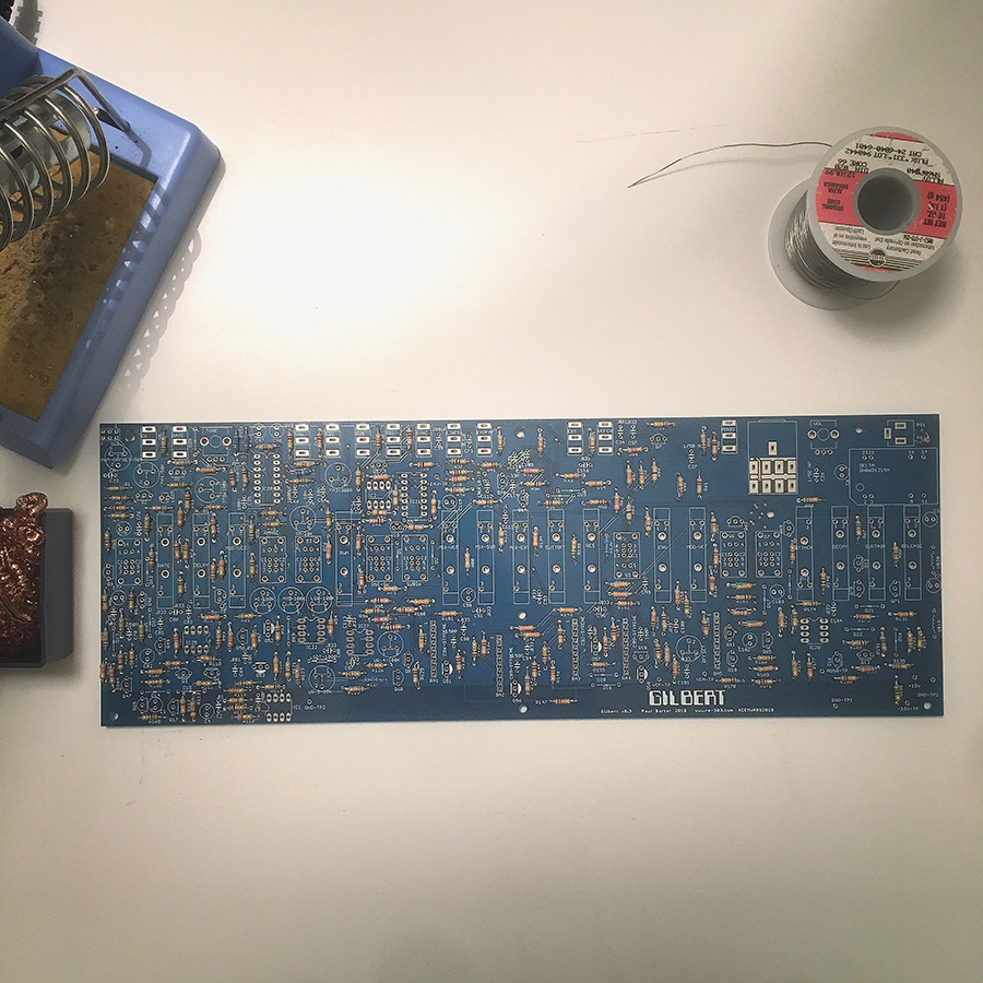
The resistors are all in place, and the build guide shows a picture and would like me to compare my work to the picture and make sure everything is kopasetic.
It’s 4:18am and can’t tell if my feet are still there or not.
My heart says “keep going! I wanna hear how this little beast sounds!”
But I’ve promised myself that I’m going to take my time, check and re check my work and learn all that I can as I go.
So I’m going to bed, and will do a visual compare and contrast in the morning (with a cup of coffee.)
Hard part is done. Now on to the interesting bits.
PART TWO – DIODES, POWER & IC SOCKETS
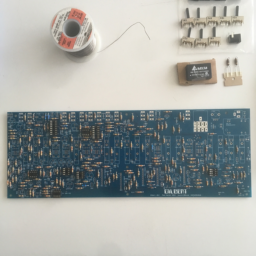
The power supply components, diodes and IC sockets are placed. Here I did a meter test of the sockets because I’ve had trouble here before.
I’ve got a light touch and that’s not always what one wants, so I tested each pin for connection.
Got a satisfying “beep” for each one.
This part was fun, really nice to be working with something other than resistors.
Now it’s time to take a little break, clear my head and when I come back it’s time to get out the volt meter and begin measuring and testing to be sure everything is good so far.
PART THREE – VOLTAGE TEST ONE
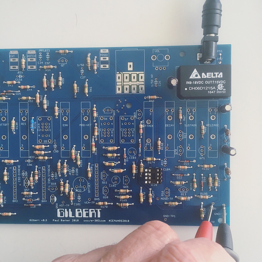
Round one metering tests check out. Kinda passed with flying colors.
Powers up and meters +15, -15 and -5v in all the right places.
IC sockets all have the correct power and it’s all within .5 vdc which is perfectly acceptable.
How exciting!
Now it’s on to the capacitors!
PART FOUR – CAPACITORS & TRIMMERS
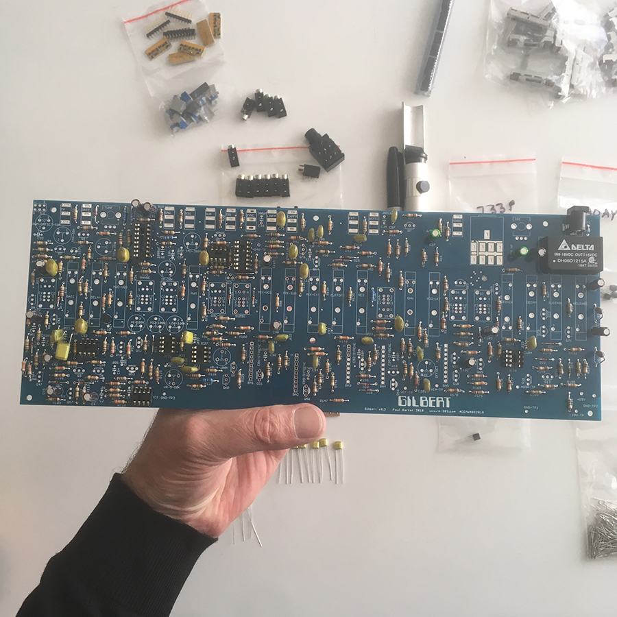
All the capacitors and trimmers are placed.
It’s getting really pretty.
PART FIVE – TRANSISTORS, POTS, SWITCHES & FADERS
Almost done.
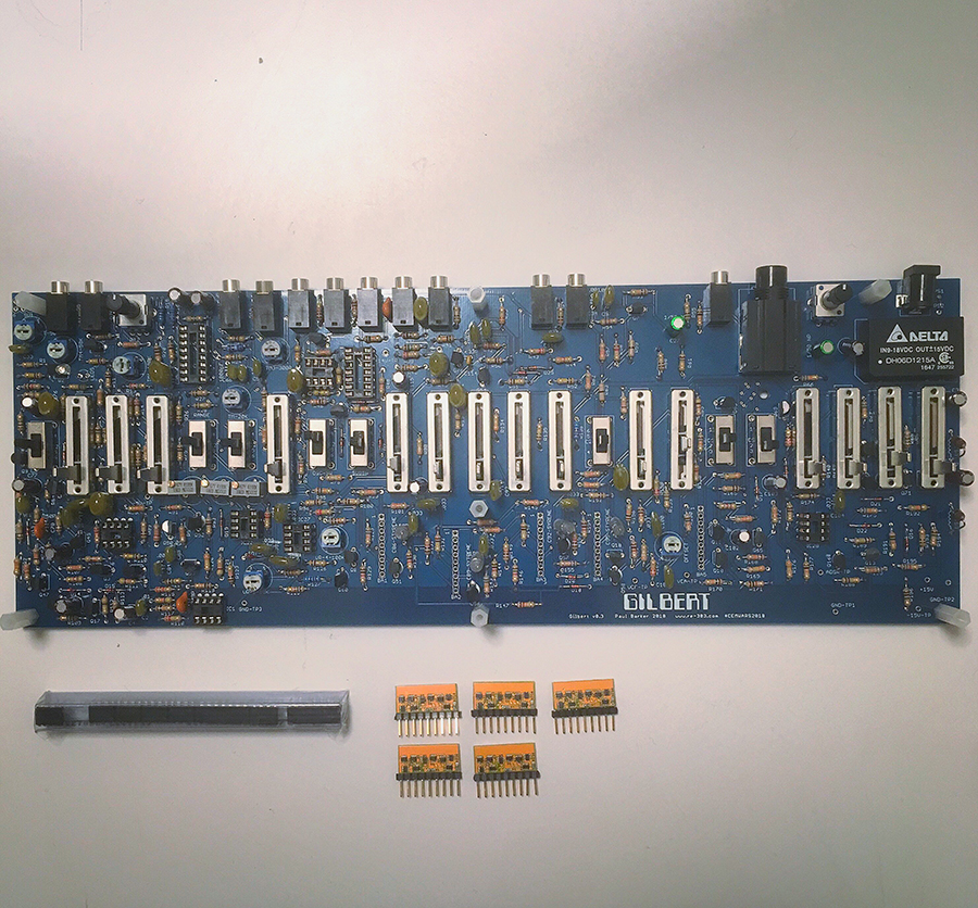
Transistors, attenuators, switches, trimmers and potentiometers are all placed. BA662 clowns are built.
Last steps:
1. Measure the voltages again
2. Install the IC chips
3. Connect the BA662 chips
4. Calibrate.
PART SIX – VOLTAGE TEST TWO
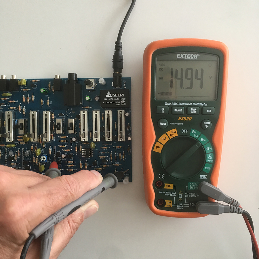
Build is almost complete. This morning’s voltage tests check out.
All measurements are within .05% of the specified goals of +15v, -15v and 5v
Looking really really good, but keeping my toes crossed.
To do:
1. Place the IC’s
5 X LM358
1 X CD4013
1 X TL082
1 X Curtis 3340
2. Get out the scope and visually test the oscillator outs.
3. Place the BA662 clones
4. Test the filer
5. Tune the VCO
6. Adjust the trimmers
7. Adjust the VCA
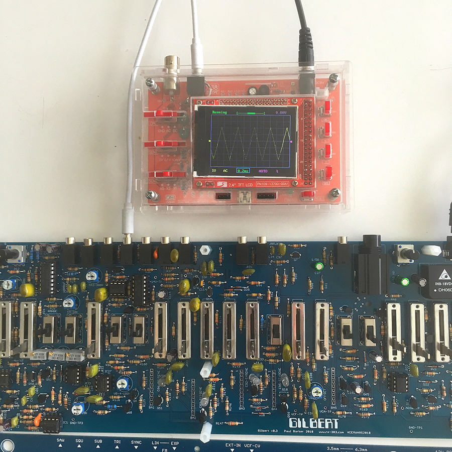
PART SEVEN – WAVEFORM TEST
IC’s are in place and Gilbert powers up without blowing a cap, or smoking. LED responds to rate, and these are the waveform output readings on my little scope, and now it’s time to place the BA662 clown chips.
PROGRESS REVIEW – HERE’S WHERE WE ARE NOW
Pretty cool, right?
PART EIGHT – OSCILLATOR CALIBRATION
There are a few things to say about how to calibrate the oscillator. Initially I measured and started turning trimmers and got frustrated because I was just kind of tuning up, and then tuning down, and then tuning back up, and then tuning back down and getting nowhere.
Tuning With A Digital Multi Meter
First thing? I didn’t understand at all was how to measure the voltages with my DMM or cheap DIY scope. Here’s what I learned about that today:
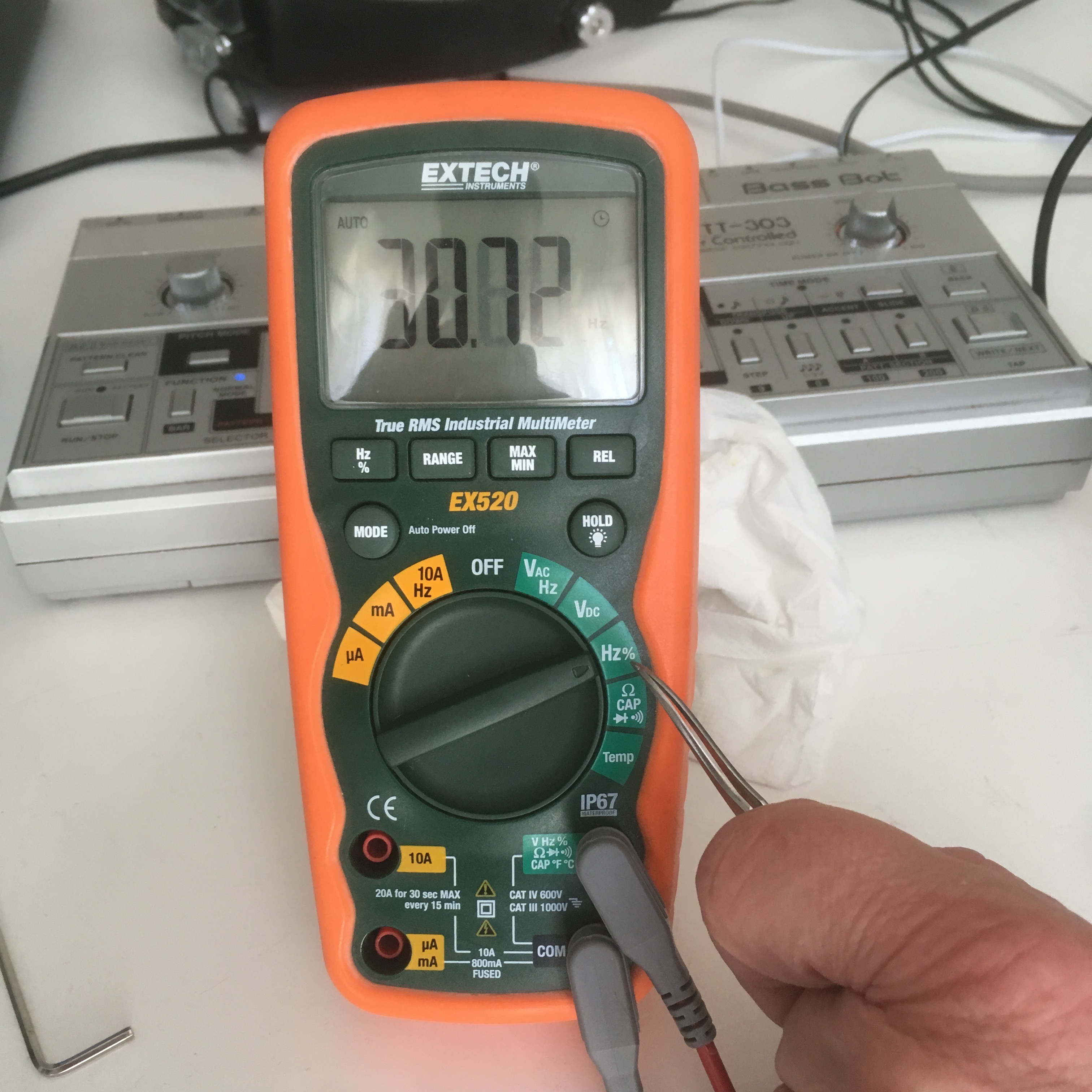
Set the DMM to Hz% (see above)
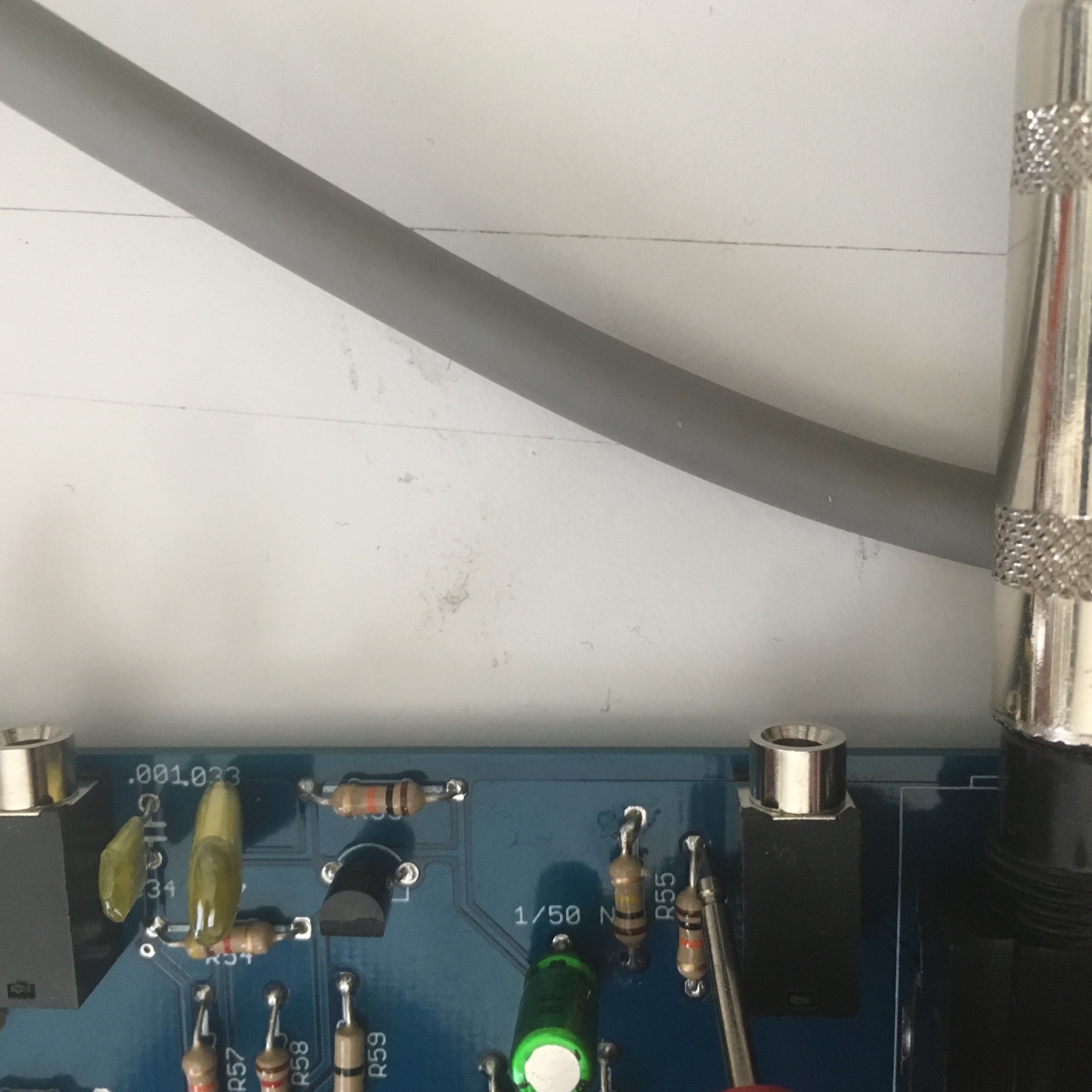
The output of the 3.5mm jack has a resistor beside it, and if you dig the positive tip of the meter’s probe into the top of that connection, with a ground of course, you will get the measurement you’re after.
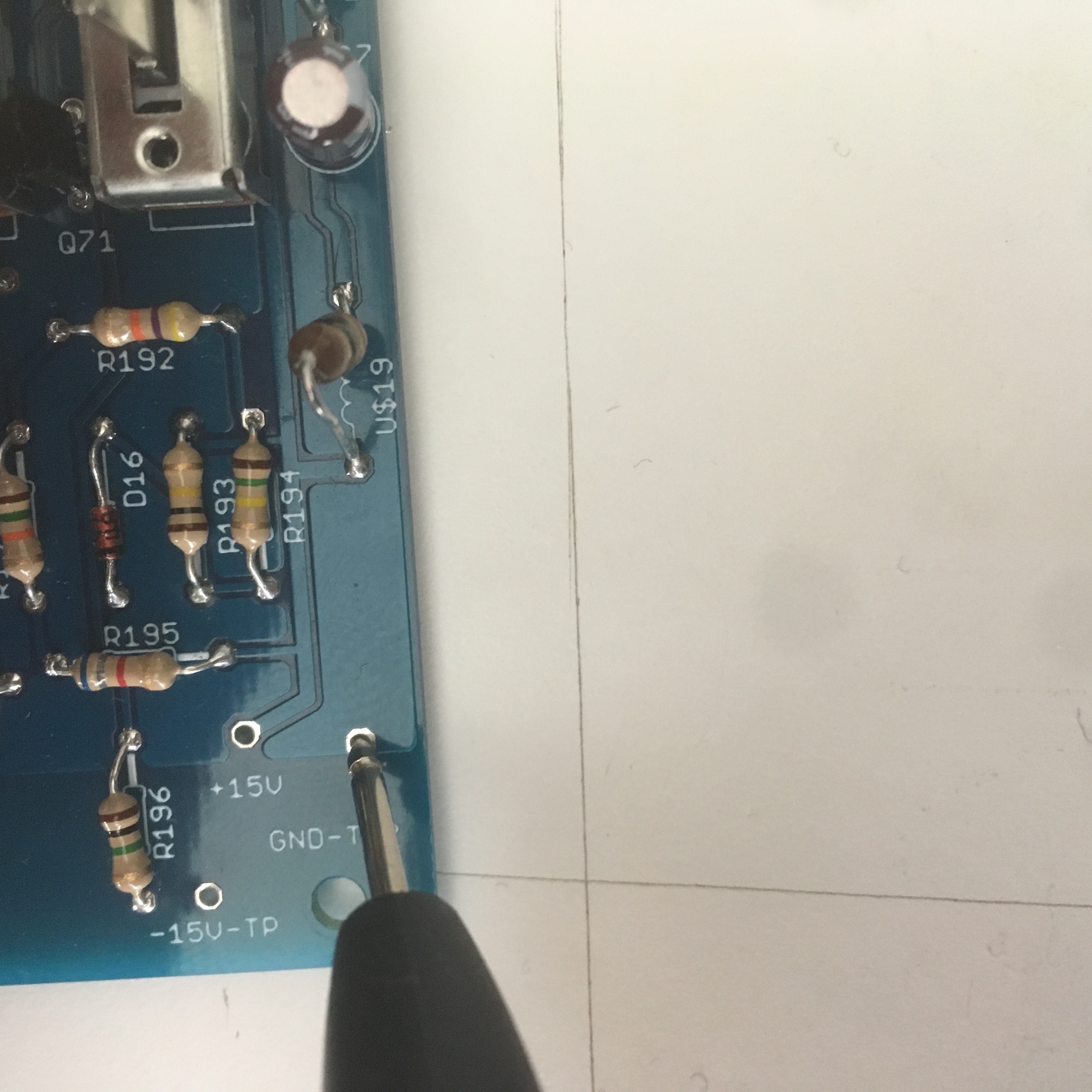
Ground from the basic ground, the same one you did the voltage testing with.
Successful procedure for 1v/Oct tuning
Before you begin, make sure your tuning pot is at 12:00. I did this the first time and it was set to 3:00 and I knew that needing to have my tuning pot at 3:00 to have Gilbert in tune was? going to annoy me, so I tuned it again with the pot in the center.
What I didn’t understand what what we were actually trying to do. I’m sorry if this is sully, or pedantic, but I really enjoyed my mind going *boom* when I finally understood it.
There are 2 things happening:
1. We want to set the width of the voltage. This is where we calibrate one complete octave between C1 and C2. It’s adjusted with the single rotation pot – TM3-300R and if you play a C1 and note the voltage, and then a C2 and note the voltage you’ll see your current spread. The spread can be adjusted with TM3.
It doesn’t matter if you’re setting it at 26.5 – 53 or 75-150. What we’re looking for is a 50% increase from C1 to C2. So this step is only about setting the width.
2. We want to accurately tune all three of the multi turn trimmers and accurately tune the Lo, Mid and Hi settings correctly.
Starting in the Lo position as directed in the build guide, now play a C1 and tune the Lo pot (far right) to 55hz. If you’ve done the width correctly, then playing a C2 should report an output of 110hz (50% increase)
Then do the same with the Mid and Hi settings. But note that Mid will report 110hz at C1 and the Hi will report 220hz at C1
What to do if this isn’t what’s happening
Go back to the width pot – TM3 – and re measure your spread between C1 and C2. Fine tune and adjust this until it is in fact a 50% spread. ie: 25 – 50 or 55 – 110
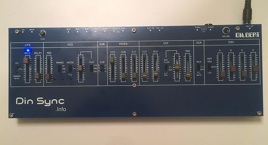
PART NINE – COMPLETE
That’s the build from start to finish, but I have some notes for you.
1. FILTER CALIBRATION
The build document asks us to turn the resonance up all the way and then send in 1V (C1) and tune that frequency to 1Hz and then do it again at C2 to get 2Hz. I was not able to accomplish this. By the time I got close to 1Hz the resonance would drop out completely and be gone.
So what I did was I just tuned it to where I thought it sounded pretty close, and good to my ear. This isn’t correct. This deserves a little more learning and a little more time from me to to figure out both why it’s dropping out of resonance at this stage, and also how to calibrate the filter properly.
2. BA662 CLOWNS
These are great. They are SMD chips collected onto little tiny circuit boards and then added to parts which allow them to be used as through hole components in this project. The BA662 was a proprietary Roland part which is no longer available. You can find them sourced from old Roland gear and buy them second hand, and there are also a few different people making clones in a number of ways. These “clowns” are lovely, and smart and work very well.
3. VCA CLICKING
While first testing and listening I didn’t like the VCA clicking like crazy. There’s an attenuation pot for this to turn it down. However, I’m noting it here that after exploring the finished synth a little bit, the range is so wide that I ended up turning the VCA back up to bring more of the click back into the sound. It somehow makes for a more classic SH-Mono Synth sound, and I like it better then if it’s just beautifully creamy smooth.
4. 12 VOLT GATE
This kit asks for a 12v gate to open up the VCA. There’s talk of Paul from DinSync coming up with a modification which involves perhaps just a few resistor changes in order to open the VCA with a 5v gate, but it isn’t available at this writing. If you aren’t sure what this means to you, understand that these days most synthesizers, sequencers and what not offer a 5 volt gate output to make things happen. The 12 volt experience is that of something vintage like a TB-303 gate output (did you know you can sequence other things with a 303?)
I came up with a basic workaround for sequencing Gilbert with something other than my 303.
1. Make Noise Maths Channel 2 attenuator turned all the way up will bump up a 5v gate to something strong enough to produce sound on Gilbert.
2. Mutable Instruments Stages in hold mode will also amplify the 5v gate and allow a little bit more control over it than Maths does.
So I have been going further with Gilbert, and sequencing the mono synth by modifying the gate output of whatever sequencer I’m using through the modular and getting a 12 v pulse to open up the VCA very easily.
I don’t usually like using my modules for basic utilities like this. It irritates me and I plan to preform the modification for a standard 5v gate once it’s offered, but in the meantime I think this sort of workaround is a bette idea than mixing and matching resistors and risking messing up the synth on my own.
MODIFICATION FIX
If you would like your Gilbert to work using standard 5v gates to open the VCA then here’s what I’ve done to mine:
• Locate R164 on the PCB
• There should be a 330k resistor in there.
• With your iron and a solder sucker gently heat and remove the solder until you are able to carefully remove the 330k resistor.
• Once removed, place a 1M resistor in R164, solder and clip the legs
I am experiencing superb results from this simple modification and can now use Gilbert with anything I’d like to use it with. Doing this does not remove the TB-303’s ability to open the VCA, it simply includes other devices as well.
FINISHED GILBERT TEST
There are a few things happening here, but first I wanna tell you about the ADSR adventure.
Upon completion of the Gilbert I felt that is blown it somehow on the envelope. Felt more like at AR than a proper ADSR. Talking when Paul and posting in the forum only confirmed that indeed nobody else was experiencing this and I’d done something badly.
Reflow, inspect, reflow and inspect again and my work looked solid. But then I noticed that the diode indicators on the build document are a little blurry and maybe I’d placed a few of them the wrong way around. So I removed the diodes from D21, D25 and D18 only to learn that they had been in the right way around after all. So I put them back.
Well, you can see for yourself that now that I’ve put them back it’s a tight little SH style envelope and whatever I did seems to have set it all straight.
The 303 is sequencing Gilbert here, and maths is receiving a multiple of the gate output.
Ch 1 of the Maths is going into the VCF input of Gilbert and is then cycled and manually ratcheted for stuttering disco action.
Sounds absolutely great. Can’t wait to get this lovely little mono synth into a huge sound system and see what it can really do.
I hope this have been a fun read, and gives you some inspiration to build (or work out the hassles) with your own.
LOVE //

6 Comments
i just made my first bottle neck slide…came out ok for my first try……chillbillie bluesgrass funk here i come
so nice.
You’ve been a gear head forever. But my heart warms seeing Sunshine Jones w your hands on eurorack. Only good things can come from this.
my boyfriend is building one too! so cool!
Dope!
What’s up! I remember when I first met you at DNA Lounge an age ago. You hadn’t even released your first music at this point, but I could tell you guys were on point.
Thanks for putting this together. I just received my Gilbert and am reading up and planning my assembly.
Your journal was really helpful and I will be reading it a few times before I start.
Also, since I am here feeling grateful, thank you for the SE-02 missing manual as well. Not to diss Roland too hard but man, those map-manuals are dreadful.
Be well.
Artist formerly known as Jeff Taylor. (Ghost of Hardkiss, Ultraviolet Catastrophe)