Roland MC-500B OLED Display Upgrade
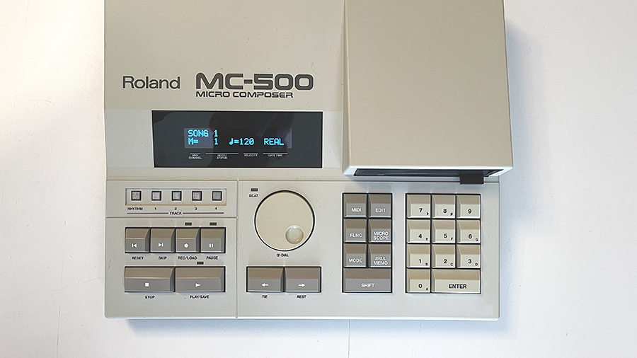
ROLAND MC-500B (MkII) OLED UPGRADE
The LCD display screen of my Roland MC-500 had seen better days. I opened it up to take a look and considered that I could potentially replace the light from behind the LCD and improve things, but these have a tendency to dim and die so I wondered if there might be a better way. My friend John Topley recently scored an MC-500 with an OLED screen and I was very curious. I looked around and found people selling $50 replacement back lights, and $100 kits for the OLED display. That seems excessive to me for a fairly unpopular sequencer upgrade/restoration and so I continued and found AMSynths had done a lot of cool updates to their MC-500 and so I looked for their suggested Newhaven 2×20 NHD-0220D2W-ABJ drop in replacement OLED. Sadly this part isn’t made anymore. I wrote to Newhaven (three times,) asking if they made a suitable replacement and they never replied.
Then my friend John let me know that his particular OLED is actually a Newhaven NHD-0220DZW-AB5. This is a part which is still available. I found one on Mouser’s site for $28. So I ordered it.
Before you begin this, please be aware of a few limitations of this upgrade:
1. BLANK SCREEN AT STARTUP
The LCD Assembly of the MC-500 and MC-300 must be handshaken with the boot rom at startup. This means that the CPU is looking for the display it is expecting. Since we are replacing it with something else the boot loader will not find what it’s looking for and it will “crash.” This means that if you don’t have a disk in the floppy drive at start up, it will simply show us a blank screen.
To correct this, insert your software floppy, and restart the machine.
2. AVAILABLE MEMORY DISPLAY
Two others who have attempted this update have reported that the AVAIL MEMO button displays no data.
To correct this, press and hold SHIFT while pressing the AVAIL MEMO button and the available memory should be displayed.
Apart from this, there are currently no other known hassles associated with this modification.
Here is the process of replacing the original LCD display assembly with the Newhaven NHD-0220DZW-AB5 replacement OLED:
This is the original LCD assembly from the stock Roland MC-500 and MC-500mkII

This is the original LCD assembly removed. It comes out by disconnecting the power connector from the power supply, removing two screws, and then slipping the assembly out of the two plastic clips which hold it in place at the bottom.
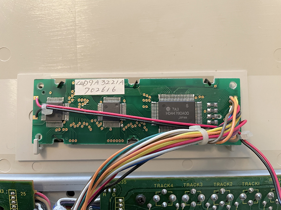
This is the reverse of the assembly while still mounted. Note the screws on the top, and the plastic pieces which hold it in place on the bottom.
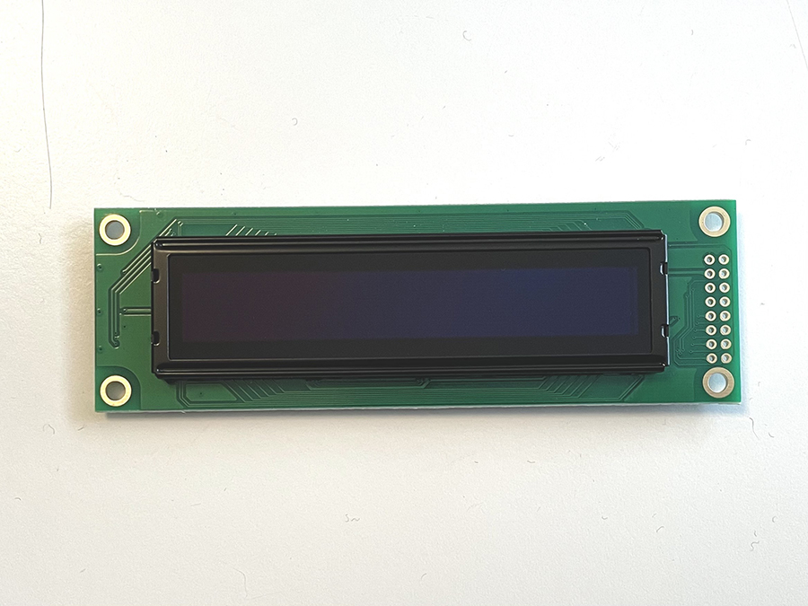
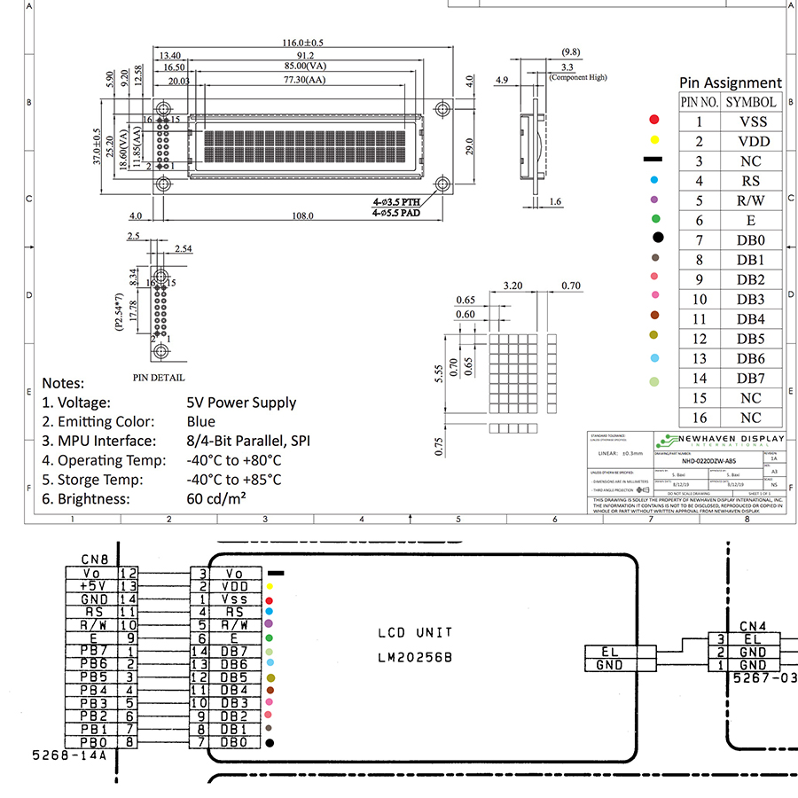
This is the Newhaven NHD-0220DZW-AB5 replacement OLED from Mouser.
Now it get’s interesting:
It’s a drop in replacement, but if we just haul off and desolder all the wires chances are we will make a mistake.
So I compared the schematics for both the replacement (above) and the original (below) and the pins all match up.
The pin out starts at the bottom and the stack, so 1 is below 3 and 2 is below 4 like this:
º 16 º 15
º 14 º 13
º 12 º 11
º 10 º 9
º 8 º 7
º 6 º 5
º 4 º 3
º 2 º 1
Also note that pin 3 is used on the original LCD but it is marked as not used on the new OLED (I connected it anyway.)
How I did this was I simply went one pin at a time, removing a wire from the original LCD, and then connecting it to the corresponding pin on the new OLED. One by one until they were all connected.

You can also remove the voltage transformer from the power supply board (see above here). You don’t need additional power for the new OLED, so if your VT is noisy (which sometimes they are) you can remove these parts. I left mine in because they aren’t noisy, and also I never know what I’m going to do, and am often so smitten with stock things that I may at some point want to restore it to stock and that might be handy to still have these components in place if that strange day ever arrives.
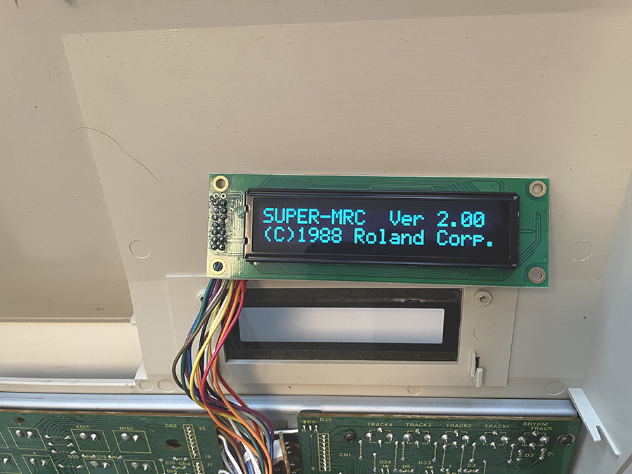
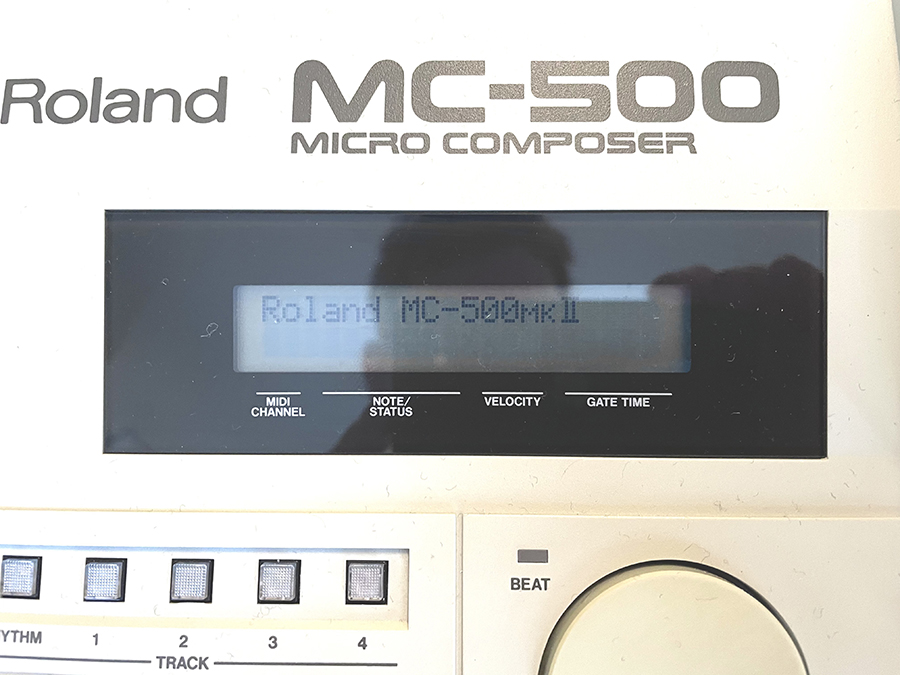
So then it was time to test it.
At first attempt it was a thrill to see Roland MC-500 MKII across the screen (mine is actually an MC-500 upgraded with the OM-500 motherboard to present a MC-500B – effectively the same as a MKII with more ram, and a different processor) but then it went dark. Typically the screen says “no disk, please insert it!!!” or something like that, but it didn’t. It was just dark.
So I took a closer look at my soldering, and found three or four manky connections which I fixed, and then I tried it again, and everything was perfect.
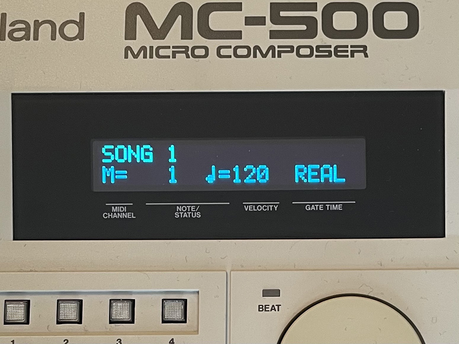
This is the final result, installed, assembled, and working. Lights up beautifully, fits in perfectly, and looks just wonderful. $28 and time well spent. Much improved!
Along the way I discovered that my particular unit is not a stock MC-500, but rather it is an MC-500B which is a Roland upgraded circuit board delivering more ram, and a different processor, effectively making it an MC-500 MkII. As you can see in the comments below, at least two people who have attempted this OLED upgrade on a stock MC-500 have had a couple of screen failures. The OLED works, however, the screen which asks us to insert a disk when powered without one does not display, and the Available Memory function also does not display. However, it does display correctly for my MC-500B.
This leads me to believe that it’s possible that this procedure is actually only recommended for the MC-500 MkII and not advised for a fully functional MC-500.
I haven’t got access to the MkI service notes, so the mystery of what’s potentially different or going wrong between this model OLED and the MC-500 MkI persists.
I hope this inspires you to improve your circumstances, and helps you to make music, and restore these wonderful things we love so much.
Enjoy!
24 Comments
Great work!
Awesome !
Very nice! I have two old rack units in need of the same treatment, just have to get a parts list together. So much fun!
Beautiful <3
Hi, I just did this and also have the black screen instead of “ Insert Disk “ don’t see any bad soldering, though. Do you remember which pins you resoldered? Also just want to confirm that each of the pins matches to where the old display’s pins were connected. ( except for 15, 16 ) – and that you left pin 3 connected and the old backlight transformer in place- thanks!
@Paul – I did connect pin 3. I also did not remove the transformer, but it isn’t plugged into anything (because the new OLED doesn’t have a connector for it).
After I got a blank screen, I re-flowed the whole thing, used a visor to see that everything was well connected. After that everything worked fine.
Try powering it up with the disk installed.
I reflowed a couple times, and even installed another display, still have the blank screen instead of insert disk, and also my stop button doesn’t work at all, but that may have been from a spill, ha ha. what’s interesting is that the service manual mentions an update on the system ROM to correct the problem with the screen not working correctly in disk mode. Oh well- I think I might just replace the backlight on my regular mc500, as the transformer is pretty quiet on that one.
All the other screens seem fine – I am so curious about why that one message doesn’t show up! Oh well- thanks.
@Paul – Very curious.
These buttons are mechanical, so it’s possible that cleaning them out will make them function again. You probably want to keep alcohol out of them, I’m not positive how the contact scheme works, but whenever there’s a conductive disc of any type isopropyl alcohol will ruin them. Best to stick to a drop of dish soap and warm water, and compressed air.
My friend John has trouble with the Available Memory displaying blank on his (same OLED as us) and we haven’t been able to determine what’s wrong for him.
I’m really curious actually. Like why does mine work, and yours is blank on the disc message, and John’s is blank on the Available Memory message?
Perhaps there’s more here that we don’t know we don’t know?
I’d love to know and find a solution for all of us (and everyone else.)
I tried to get it that button but the way the panel is designed it seems it’s impossible, unless I dump the whole thing in some thing
I also get a blank screen on the available memory page
@Paul – Well that’s vexing. What a drag. You seem to have both of the issues. I’m sorry about that.
I don’t understand why mine would be as expected, and both yours and John’s are struggling with the available memory. If it were mine I would carefully go over each connection and be sure that each wire was properly connected. The points are not exactly the same. And the OLED is inverted (as noted above) and it’s possible that something got mixed up. I did mine one wire at a time, and went by the schematic to make sure I was connecting the correct point to the correct point – as the LCD assembly and the replacement OLED are different.
I couldn’t tell from the schematics which connection is intended for which function, or why something might work or not work.
Frustrating.
Mine is working fine, and I haven’t done anything more than I have said in the article, clear notes against the schematic, and connection followed by the reflow and it’s fine.
John’s unit is a 220v being used in the UK (240v) while mine is 117v being used in the US (117v). Is yours by chance a European version as well?
What do you mean by
“The points are not exactly the same. And the OLED is inverted (as noted above) “
In the article it says that the pins all match up, and my oled is not inverted, it is positioned the same as the original, and each wire is goes to the same point as the original as well.
Mine is a MKII, US version.
Thanks
Paul
Oh , I get it, you mean the wires are inverted but they are all still in the same order, correct ?
Mine are hooked up starting with the right side of cn8 (labeled #14) ie gnd, connected to pin #1 of the oled (gnd) , then #13 to #2, etc in order. Skipping over pin 3 of the oled, oled pins 15 and 16 unconnected. I confirmed this with continuity mode on a multimeter running down the line sequentially.
Is that how you hooked up yours?
@Paul – As I illustrated in my essay here, I compared the schematic of the original LCD assembly, and the replacement OLED and then one by one placed each wire.
So point to point, one at a time. I didn’t make any assumptions, or take anything for granted. I just went slowly and connected DB0 [7] on the schematic of the LCD assembly to DB0 on the OLED [7] and rather than being concerned with colors or matching up the array in terms of color or what it was like before, I literally placed what was supposed to be connected to where the OLED schematics asked for them.
I am naturally prone to “thinking I know” and also love to just pull all the wires out, and this often leads to errors I obviously have to figure out and re do. I’m getting sick of doing everything three or four times and trying to develop the habit of making notes, drawing diagrams, even running them past people before I haul off and ruin things. I’ve ruined a lot of lovely things.
So you don’t remember if pin one on the old display corresponded to pin one on the new display, pin 2 to pin 2, etc. from one to 14. ie when you were doing it one wire at a time did it end up going in order or skipping around. ?
Thanks
If you take a look at the two schematics, above, you see that the pins do match up, however they are not listed in the same order.
So for example the pin order of the original LCD display assembly is actually:
3, 2, 1 , 4, 5, 6, 14, 13, 12, 11, 10, 9, 8, 7
This is how they are illustrated in the schematic.
And the original LCD assembly board is not numbered (on mine)
I traced these pins back to their sources on the connector/IC and made sure that they were correct on both the LCD assembly, and the PCB itself. From this I created my color coded diagram (matching the wire color to the function of my particular unit) thus avoiding the confusion of un numbered pins.
The pin order on the OLED assembly is more straightforward, but it is inverted from the schematic. The schematic shows the top view, and we aren’t inserting into the top, I soldered on the top, so the pin numbers are mirrored.
So on the back, where I installed the wire the pin out is:
15 – 16
13 – 14
11 – 12
9 – 10
7 – 8
5 – 6
3 – 4
1 – 2
However, on the front where the soldering is happening the pin out is reversed:
16 – 15
14 – 13
12 – 11
10 – 9
8 – 7
6 – 5
4 – 3
2 – 1
And I connected the function/color to the correct pin on the OLED as directed in the schematic.
So for example: DB0 is a black wire (on mine) and it was connected at the bottom pin of the LCD assembly originally, but it is noted on both schematics as pin 7.
So I installed it into pin 7 on the OLED.
Source, function, schematic, destination.
They do not line up, they are not the same or in the same order. This is why I did it so slowly and took notes to be sure I was connecting the right things to the right places.
Sorry, not trying to give you a hard time.
In you picture of the original display, the black wire is clearly not attached at the bottom.
I spent a lot of time studying the schematics, and realized that the diagrams do not show a visual representation of the actual display board or the CN8 connector, they are numbered, so even though db0 is shown at the bottom of the display board in the diagram, it is numbered pin7, which would not be placed at the bottom of a 2×7 arrangement of holes.
The bottom pins would have to be 1 and 2, or 13 and 14,
In the schematic, if you start with pin one of the CN8 connector and continue counting to 14 you’ll see that it is simply the reverse order of the pins on the display. at least that’s what I figured and why I wired it that way and everything works except for those disc and memory screens.
I figured out that my stop switch itself is bad and I have taken it out and I’m going to clean it. Also it’s interesting, my MarkII is completely different inside, has a wimpier power than the regular mc500, and no chassis ground that I can see. The wiring harnesses to the chassis board are so different that it’s impossible to swap them.
Also the service manual mentions an update for the OS chip to fix display issues while in disk mode. Which I thought was interesting.
Thanks for taking time on this, once again not trying to give you a hard time, I was thinking that maybe it needed an earth ground on pin 1 of the display or something.
@Paul – I actually find it fascinating. I think you may be on to something with the MKI/MkII issue. It seems that John and you both have a MkI and I have an MC-500B which is the MC-500 upgraded to a MkII with the Roland upgrade board.
It’s interesting that you both are having an issue with the Available Memory display. I have not seen a copy of the proper MkI service notes. I wasn’t able to find one on the internet, and so I just used the MkII service notes and assumed that its notes within would sort things out.
I’d be very curious to see a copy of the MkI service notes and see if it makes any notable or potentially correctable differences. However, it’s also possible that the MkI PCB isn’t a perfect drop in replacement candidate for the OLED. Perhaps it only works on the MkII and the B upgrade board?
On an original MC500 with OLED, press SHIFT and AVAIL MEM to get the available memory display.
It looks like the earlier Boot ROM (2.3) in the MC500 is struggling to handshake with the OLED, pressing keys eventually gets a partial message back up. The same problem happens in the MC300 with a later and improved Boot ROM but this crashes completely. The MC500 Mk2 also has an improved Boot ROM so maybe this version (1.02) works ok.
At least the workaround is easy.
@Rob – Agreed. I don’t think asking us to press Shift + Avail Memo is an issue for displaying the available memory. Now that we know that’s what’s required it’s cool. The boot loader crashing without a disk inserted is another matter. Unfortunate, but I can live with needing to have a disk inserted in order to boot. After all, it’s looking for the original LCD assembly, and not finding it. We have replaced it. Makes sense.
Just for clarity, the one I tried it in is a MKII, haven’t tried it on the mark I.
On a happy note , I pulled out the Stop and Play switches which had stopped working, disassembled and used dental floss on the switch plates, now they are working again- so everything is good except for those missing screens –
I just upgraded a MC-500 B with the Newhaven OLED. The “insert disk” message does not appear, but that´s o. K.
I don´t understand the problem with the available memory page. If you look at the MC-500 MKII layout the button is no longer labeled “Avail Memo”. It is labeled “CANCEL” and the Shift-function above is “AVAIL”. Same with the MC-500 B with stickers.
One note regarding the main transformer: There are no 110V or 220V or 240V transformers. All MC-500 use the same universal transformer! The only two differences are the pin where the cable at the primary side is soldered to and the different fuse values. So there is no need for external transformers!
@LOOPINO – Good to know. you know, I’ve seen the buttons with the stickers on them, but I don’t know what they say. Splitting the difference here between a MC-500 mkI body and keypad, and the “B” upgrade means for us that such stickers would become meaningful and loading the Super MRC much faster and easier.
That said, the MkI CAN load up the Super MRC, so this is all relevant.
I’m glad to know that nothing’s wrong when pressing AVAIL MEMO and the report is blank. SHIFT + results in a display of the available memory (as it should be) and I agree, living without the disk prompt on startup is ok with me too.
Better qualified folks than myself have all had a look, I’ve tried the capacitor experiment I read about elsewhere to try and slow down the timing to get a handshake when the CPU asks for it, but I’ve not been successful.
All in here, I think that I m not bothered by the need to put a floppy in to get it to boot (I gotta do that anyway) and don’t feel I lose anything else. Plus these OLED screens as just so much nicer.
On the transformer – True. An easy fix for anyone with a little soldering experience. I was working with my friend John who scored a European version “220” and needed a UK version “240” and did not have soldering experience. So we were wondering about his voltages. He has since had someone sort that out for him and it’s as it should be now.
I’m curious about getting my hands on a sticker set for my buttons. I’d love to see about that.