RE-303: Build your own authentic replica of the TB-303
I spent the last week building the DinSync RE-303.
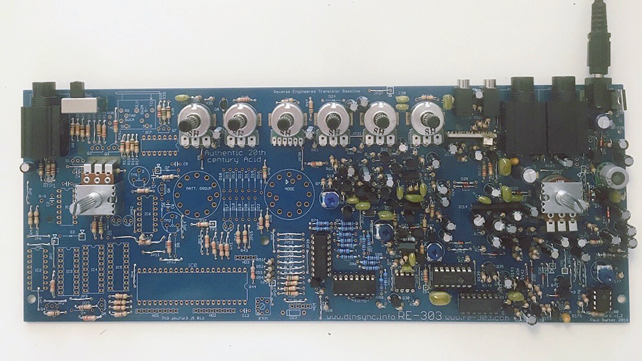
The RE-303 is as exact a replica of the Roland TB-303 as is possible. The BOM is comprised of the original parts used in the TB, and the parts and boards, case, and all involved may be considered interchangeable. Naturally most of my time was spend sourcing parts for the build, but what was I going to build? What exactly is the RE-303 and where do you get it?
Originally the project was an alpha situation. Circuit boards and moral support was all that was available, and many brave builders grabbed the PCBs and dove in. As the result some very difficult to source parts have been collected into a special kit called the Space Cadet. It comes with the circuit boards, a few rare transistors, the precious power supply coil, switches, jacks, and the potentiometers for an authentic 303. This is awesome, but it’s not everything you need.
Here is the bill of materials (BOM) which illustrates everything else that’s needed.
A few things to note about the BOM:
1. This is for version 1.2 of the Space Cadet/RE-303, I recommend you check with RE-303.com and make sure you’re getting the most current information.
2. Some of these parts are “rare” and there are no mouser or digikey numbers for them, so in order to build an authentic replica of the TB-303 you’re going to have to do some sleuthing, and some study.
The parts aren’t really rare per se. What they are is out of production. The original parts used in the TB-303 were garden variety components, found in toasters, radios and lawnmowers and everything at the time it was produced. But a lot has changed since 1982 and many of these parts (notably the transistors) have faded from use and supplies. So while they aren’t expensive, or precious, they are not parts you can just pick up anywhere.
Here someone called Obsoledo has gone to a lot of this trouble for us. He makes a mad comparison between 4 different varieties of transistors and comes to the conclusion that it doesn’t matter which transistors you use. That’s pretty heroic for such baleful results, but listen to the sound cloud samples and hear for yourself. I am very curious about a few of those combinations, and am considering modifying my RE-303 and adding sockets for the VCF and VCA/ENV transistors and mixing and matching to see what happens. That’s my kind of party, it may not be yours. Don’t sweat it if it isn’t. The Re-303 sounds brilliant using the exact parts listed in the BOM. So you don’t really need an education in vintage electronics if you don’t want one.
A Word About Fake Parts
After I collected all the “rare” parts for my build I realized that there are a lot of bogus transistors out there. Some people are so lame that they’re selling bags full of any old component with the wrong numbers on them off of eBay, and other such sources. There are known frauds, and others who seem to be constantly changing their user names and passing bunk goods to people like us. Super weak, but I took two precautions:
1. I got up to speed on the fake parts list in the RE-303 forum.
2. I bought myself a $40 component testing box which really came in handy. There are cheaper ones, there are kits to build them, and there are fancier ones, but this is the one I got.
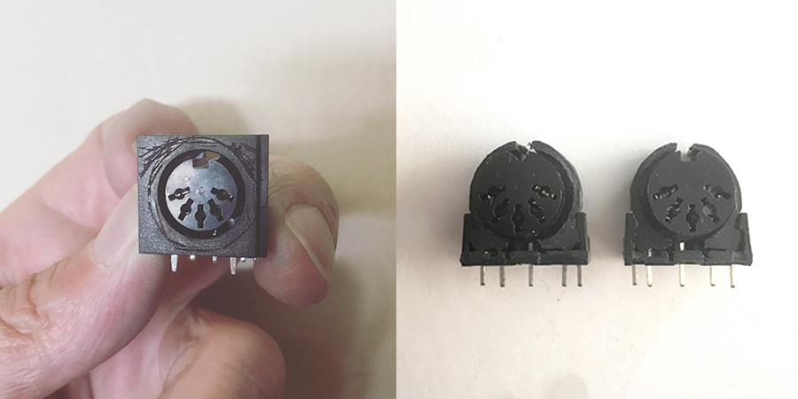
The Extinct Din Sync 5 Pin Connector
The build guide, and the BOM say that there are no longer parts like this, and they must be fabricated.
That sounded like something I would totally screw up. But it isn’t as terrible as it sounds. A file, and a vice and some patience and it’s done in a few minutes. Here is a picture of what I began with, and the two after they’d been filed down. Not so bad really.
BA662
You’re going to need a Roland BA662 (1) to complete your build. This isn’t included in the Space Cadet kit, and in fact they have become quite impossible to find. I bought one which had been rescued from a broken piece of gear for $25 a few years ago, but when I checked it out again for this build I discovered they could not be found for less than $50.
Thankfully Open Music Labs have come up with a clone of this vintage IC for around $10.
You can buy them in the RE-303.com shop, or directly from the maker through Synth Cube. There are a few other alternative clones popping up these days, and some of them look pretty cool. I wrote to all of them and didn’t hear back from anyone about size, shape, or availability. So I went with the version in the RE-303 shop.
You don’t have to add the little SMD trimmer or resistor if you don’t want to. I’ve listened to them both and sonically there is no real difference, however, the little tiny trimmer on the clown allows us to turn down a clicking which is produced by the VCA. Some of you might like that sound and want it, others might be endlessly irritated by it. Before you choose, give my video clips a listen and see if you can hear it. If that sounds good to you, then forget the SMD parts. If you aren’t sure, then get them and add them later if you want them. But remember to make this decision before you install the BA662 into the RE-303. ‘Cause there is no way you’re going to be able to add them later. I mean, I suppose anything is possible, but man… what a drag.
RE-303 CPU
You can absolutely drop your vintage TB-303 CPU into the RE-303. So if you have one laying around, or you’ve got a crushed 303 in a box somewhere this is the project for you to revive that beautiful thing and get it working again. I bet there’s a legit BA662 and the elusive yellow coil in there too.
But if you’re like me and your TB-303 is a memory, lost in the fire, stolen, or sold to pay rent then you’re going to need a CPU to get your baby together. Mercifully the Space Cadet kit comes with the Sonic Potions RE-303 CPU.
However you can also use the Quicksilver CPU if you prefer. As I said before, this is a fairly precise duplicate of the TB-303 and with the exception of placement part numbers, and a few necessary adjustments the parts are interchangeable. So this could be refuge for a dying 303, or the birth of a brand new one.
The Case
At this writing there are two options for cases:
1. The print out your own case and snap it together version.
2. A user named SubStyler on the RE-303 forum makes a beautiful metal case which ships from Germany.
I wanted the metal case so I didn’t do any further research on the DIY case, and wrote to SubStyler and asked him about his cases. He replied and advised me that they were completely sold out, and needed at least 100 buyers to do a run of them. I was bummed, and almost didn’t decide to do this as the result. Just as I was considering giving up, I got another reply from SubStyler saying he had some news. He was inquiring about the forthcoming case he’s designed for the Gilbert (which I’ve also built) and the manufacturer told him they had a case for me if I wanted it. I replied that I did, and this project was 100% go!
I suggest that you make a decision about your case now, before you build. The case you use will determine what parts you need, and how you will build. For example, with the SubStyler metal case you don’t need to order the midi jacks to the sync direction switch or the grounding brackets for the tempo and volume pots. But if you cut yours out of wood, then naturally you will need to get those parts. So it’s just a good idea to have a slightly broader idea of what you’re going to end up with before you start soldering. Do whatever you want, naturally – I expect you will – but this is how it seems to work best for me.
Bonus Features
The SubStyler case comes with Midi jacks, a sync in/out switch, grounding brackets, and more, but you will need to add a set of knobs to the order if you want to be sure you have the correct knobs, and buttons for the final product.
Since then I’ve learned that DinSync are planning to carry these cases in their shop soon. It’s possible that’s already begun and there’s a case in there for you. But keep in mind that they are a small company in Sweden, and things come into the shop, and then sell out. Just because something is sold out doesn’t mean you’ve missed the boat entirely. But it does mean that you may have to wait a bit. For example, I bought the last two Space Cadet kits from the shop, and about the time people started groaning about when there might be more, 20 more kits appears in the shop.
Tools
Once I got all my parts together, I prepared myself for the build by making sure I had all of the tools I needed:
First you’ll need a basic understanding of soldering
Next you’ll need a few tools:
Soldering Iron – nice one – cheap one
Solder
Trimmers
Digital Multimeter (DMM)
There’s more you might need (magnification visor, wire, cable strippers, a vice, etc.) but this is the basic set.
A word to the wise
This is not a good first (second or even third) build. It isn’t really anything I would call over the top difficult, but there are a lot of parts, and since it’s a crowded PCB your skills should be decent, and patience should be long. As we know with anything DIY the build is the fun part, and the real test of a builder is in the troubleshooting once you think you’re done.
Take a look at the build guide and you can see for yourself that it goes something like “place the jumpers” and that’s all the instruction you get.
There is a forum at re-303.com, and there’s also a face-page group, but I’ve seen a lot of inexperienced users get quickly frustrated with even terrific answers. It’s just best practice to see one, build one, teach one to know first hand what’s happening, and what things mean.
So with all of my direction, and precautions noted, here’s how my build went:
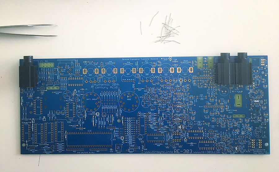
I began with the jumpers. I knew I was going to need a lot of them, so I had been saving the legs of resistors when I cut them off of other projects and putting them into a bag and keeping them for this very moment. There are 52 jumpers to place.
Next there are a few components which need to go in now because they are gonna be a lot harder to place later.
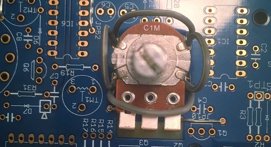
Part of this is wiring a ground harness around the two main volume and tempo potentiometers. If you are using the SubStyler case (which comes with brackets) or you’ve managed to source yourself some brackets for these pots then you do not need to wire the grounding harness. I didn’t know this, and wired it up, and then had to unwire it up once I learned that something else was going to go into these holes.
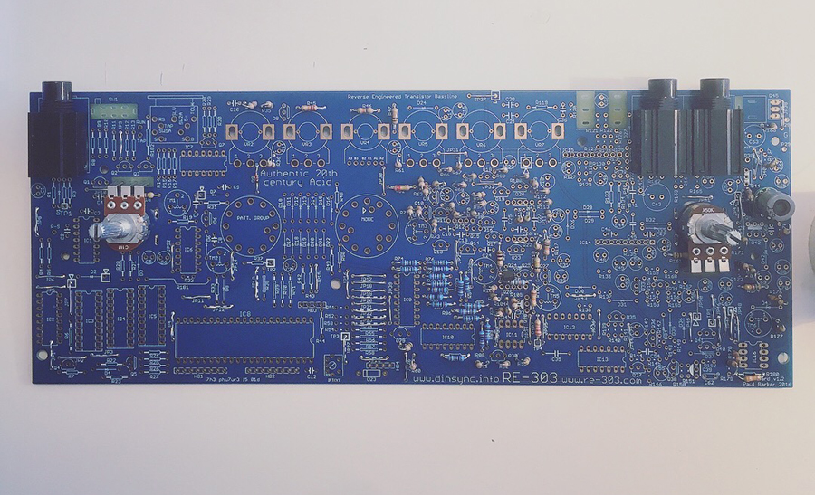
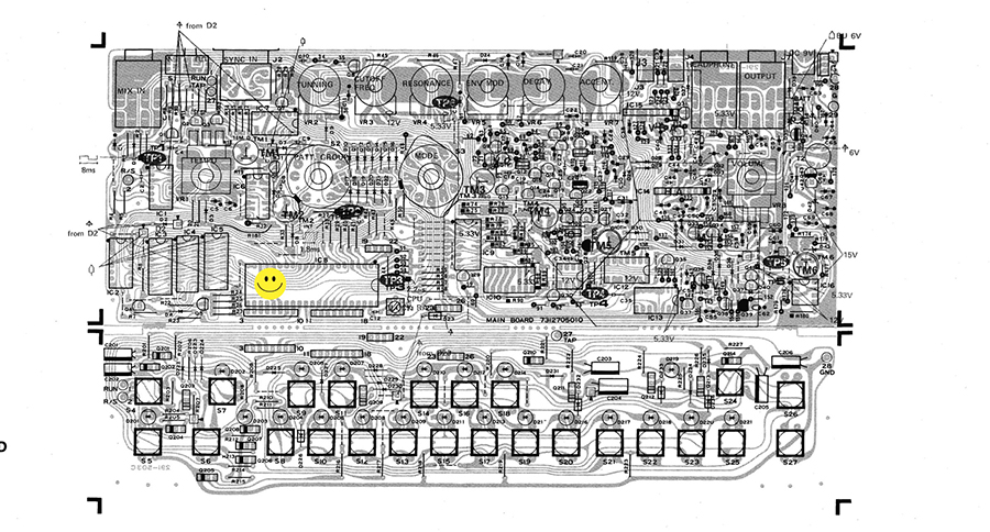
The first section is the PSU (the power supply.) See the weird grey round thing on the board in the picture? That’s the coil. The fragile little part is actually mounted onto an adapter which is seated onto some pins, and then fits right onto the board, and the other components are straightforward.

One thing to point out is the TIP30 resistor which also looks and acts like a heat sync for the power supply. I had some trouble later on where my RE-303 took about 2 minutes to boot up. This was really a drag, so I replaced the TIP30 with a 2SB596 and once the TIP30 was out and the B596 was in place the RE-303 booted up instantly.
I understand that not all of the RE-303’s respond this way, but I ordered one when I ordered my parts (just in case) and I’m super glad I did.

Once complete it’s time to test the power to be sure it’s working before we move on. We were looking for 15 volts, and I passed. If you don’t get 15 volts at this stage, do not continue. Go back, review your work, make sure everything is as it should be, ask for help in the forum. It’ll solve a whole lot of problems later, should they arise, if you sort out the project one step at a time.
Next we build the VCO. This is the heart of the sound, the voltage controlled oscillator. The VCO is beautifully simple, and there are not a huge pile of complicated things to do. Place resistors, capacitors and transistors, diodes and IC sockets and it’s done.
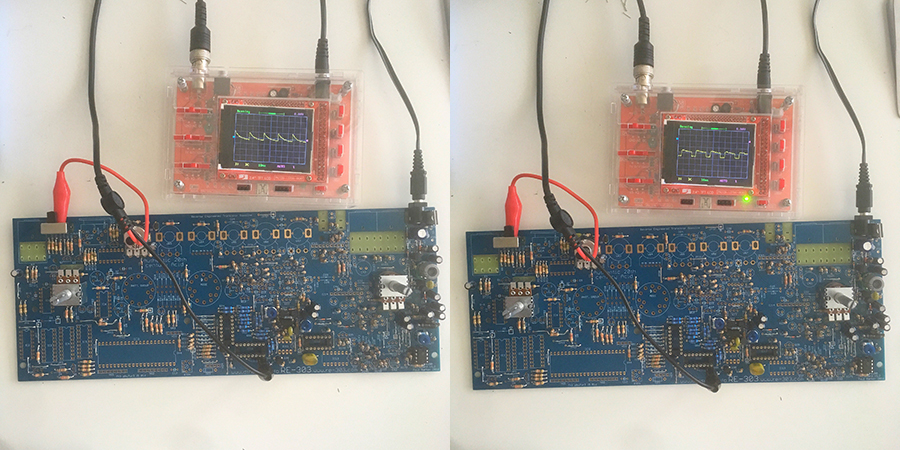
Once the VCO is done we can get our first glimpse of the sound. Can’t hear anything yet, but we can see.
I use a $25 oscilloscope kit that I got off of eBay and it’s not really amazing, but it does the job.
With this test I was able to get a look at the saw waveform and the square waveform already thumping beautifully on my little screen.
Again If you’re following along here and you don’t have these waveforms please don’t go on. Figure it out, and get it working at this stage. There’s help available for you in the forum and on the face-page group. Lots of other people have left out parts, put the wrong things in the wrong places, or just overlooked something important. You are not alone.
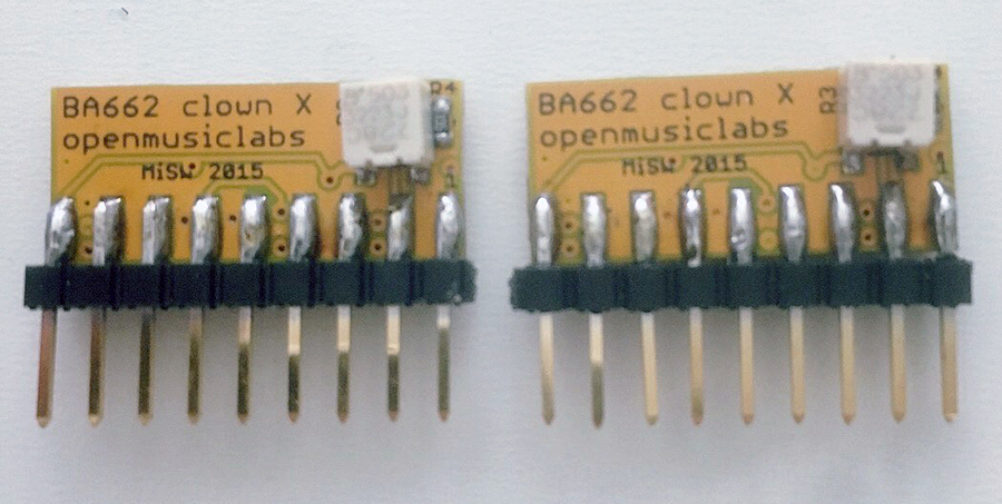
Now we build the BA662 clowns.
SMD soldering isn’t as daunting as it seems. There’s actually a happy little thrill that shoots through me when that little component about the size of a grain of sand seems to magically pop into place.
Don’t fret about it. It’s all about the technique.
From here we continue and build the Filter, Envelope, VCA and the analog section is done before you know it.
Be sure and stop and perform all testing at each stage. Don’t go forward if somethings weird. It’s important to take your time, and breathe, take breaks and be sure of your work. Undoing it later is such a drag that I just can’t stress this enough.
Next we build the digital section, place the CPU and fit the remaining potentiometers. Nothing super weird here apart from one insulted resistor, and those selector pots. Such strange beasts, but they only fit in one way, so as long as you don’t push them in too far it’s pretty simple.
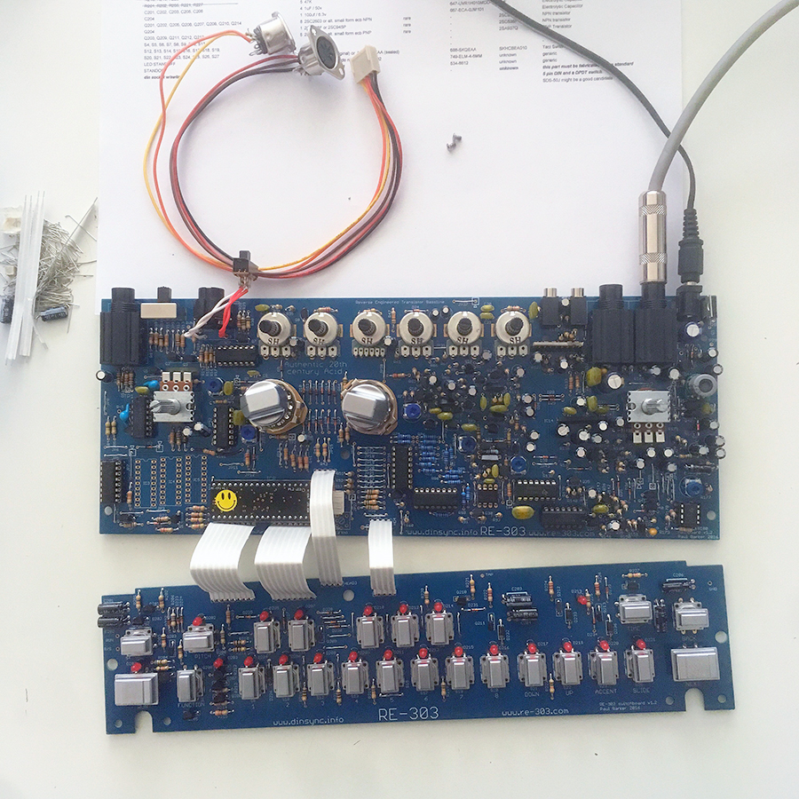
Now we build the switchboard and add the ribbon connectors. The switches which come with the Space Cadet kit are nice, Alps switches. They are sealed too, so they should give great service for years (unlike the unsealed switches which came on the TB-303 and went bad after a few years. Oh man… hours and hours of cleaning and double and triple pressing. No more baby… )
I got a little overly concerned with the pin out of the switches. The data sheet for the Alps switches clearly states a specific pin order (1,2,3,4) but the switchboard’s markings don’t call for more than horizontal or vertical orientation. So I inspected the back of the switch and saw that there is an Alps logo, horizontally across from this is a number 2. So I took that to mean, based on the data sheet that the Alps logo is pin 1, and number 2 is pin 2. And so I turned them all upside down, and was thoughtful to place them in that way. Assuming that on the PCB pin 1 is the top left in the horizontal position. Maybe I made too much work of this, but they all went in just fine, and they all work just fine, so I’m not sorry I went to the trouble.
The CPU is pretty, and the firmware is also pretty dope. It has more character than the original TB-303 firmware, so it is a little strange to make the transition, but as many compliments as I have for old school firmware, it’s really pretty bad ass to be able to change up the direction of my patterns (forward, reverse, ping pong, and random) and a lot more.
At the end of the CPU is a little connector for the cables to add the midi jacks. These get wired in when it’s time to put it into a case. Mercifully this bit can be detached and set aside for now.
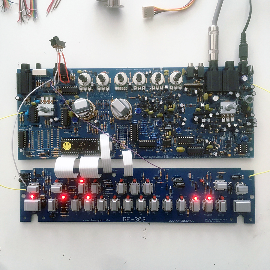
Next we connect the contact points between the switchboard and the main PCB. Ground, Tap, Run, and R/S. You don’t need super long wires for this because the switchboard will sit up on top of the main board, but it should be able to reach when it’s laying in front while you’re working on it.
I didn’t solder these directly. Instead I installed pins from a milled socket and plugged my wires into them using long breadboard pinned jumper cables. I did this so I could connect and disconnect them easily in case there was a hassle.
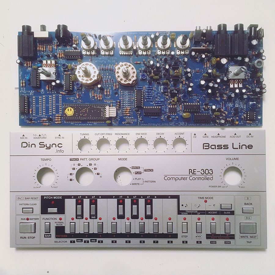
Now, if you’re planning on a case, it’s a good time to fit the panel and be sure you haven’t totally blown it. The led’s and buttons and knobs all need to fit nicely in the panel, so if you’re using the fancy one, or you’re making your own, this is your moment of truth. I did this at this point because I felt there was still going to be an opportunity here to rework components to align them better if they need adjusting.
This is also a good time to try things out and see what’s gone wrong. For my build I had a strange experience. It all seemed to be good, and then while playing around with the controls the sound cut out, and all I got was clicking.
I poked around and pressed down on a ribbon cable, and the sound came back like magic.
So I replaced the ribbon cable.
The same thing happened again once I got all that going. I was playing with the sounds and it all cut out again. Nothing but clicking.
I pressed down on one of the IC’s and the sound came back again. Puzzled, but curious I asked myself, what is happening here? When I press down, the sound comes back for a few minutes, and then for no reason I can understand it cuts out again. Is this a short in the board? No, it’s a really superb quality PCB. Have my sockets got cold solders? No way. I heated those pins and made sure they were well connected. I re flowed them to be absolutely sure, but no dice. Still nothing but clicking.
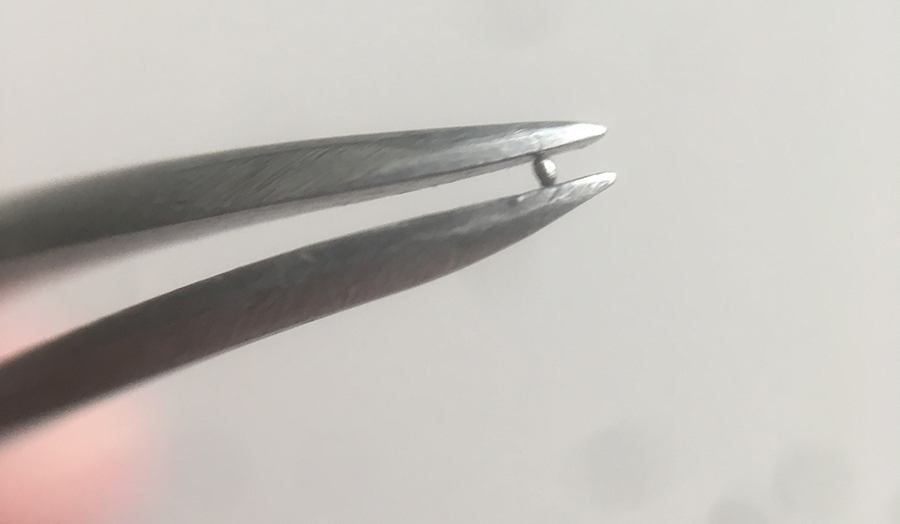
Then it occurred to me that when one pushed down on a PCB it bends. Something somewhere is touching, cutting the analog section out, and when I press down that bridge is opened and I can hear it for the short time that it remains separated.
So I flipped the board and got out my magnification visor and really gave it a close look. I found this tiny little solder ball right in the heart of the analog section. Once I removed it, the sound leapt forth and has been solid and stable ever since.
** If this doesn’t load up, reload the page and it’ll appear
Here is an Instagram clip I posted right at this moment. I couldn’t have been more delighted to have finally solved the problem, and celebrated with a little beautiful acid…
I think it’s cute that the clip is shaky. It’s actually shaking because I was doing the happy dance. I couldn’t contain my joy long enough to film a little clip for you. The 303 just does that to me.
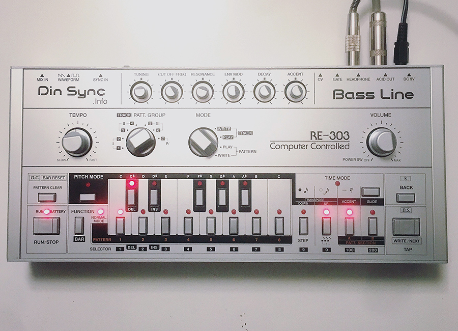
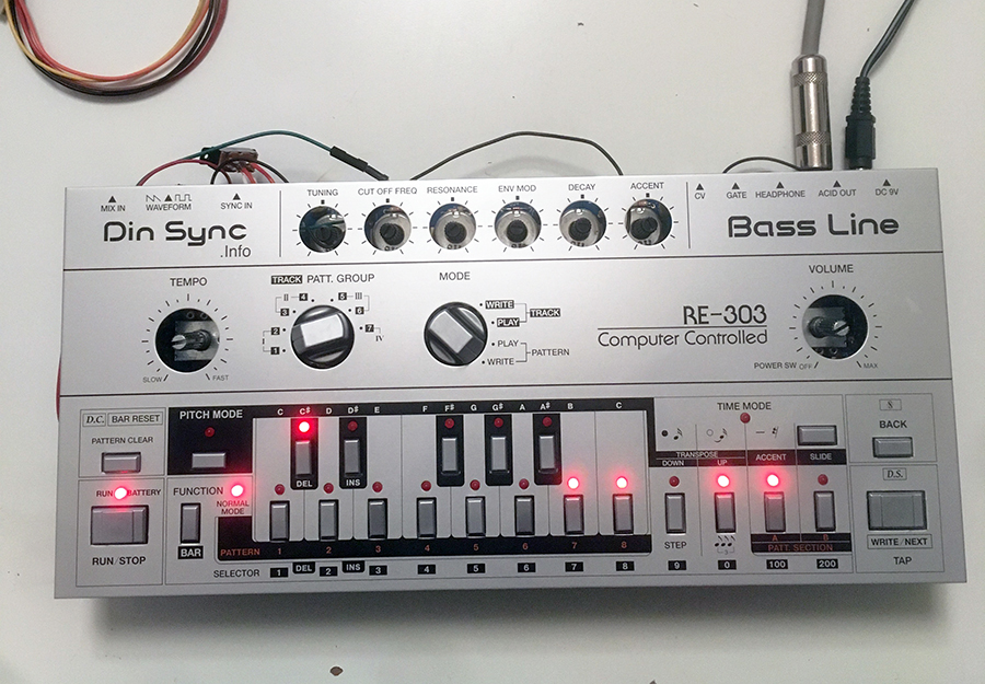
Finally I put my RE-303 into the SubStyler case and was delighted with what a beautiful thing I’d created.
But there’s one more thing we need to talk about seriously:
Calibration
There are some discrepancies in the calibration procedure of the RE-303 and the Roland TB-303 Service Notes. It’s possible that it’s a discrepancy in my ability to fully understand a service manual, that’s true. But the way I read it was that we were to use TM6 to first locate the vital 5.333 volts and then again as the width for the tuning octave. This is not the case.
Here’s how you calibrate:
1. Once you’re done with the build and everything checks out, warm up the 303 for about 10-15 minutes, and then measure from the output jack and the jumper and dial in 5.333v using TM6 on your DMM.
2. Turn the tune pot on the top row to the center.
Put the 303 into pattern write mode/pitch mode.
Play and hold a C note.
You can measure the frequency with a tuner on your phone, a DMM, or a scope. What you’re looking for is a precise reading of the frequency. Right now it doesn’t matter what the frequency is.
Now play a C an octave up.
This frequency should be exactly 1000mv higher. Or read out at precisely the same pitch on your tuner.
Adjust TM5 until this is true. Little movements go a long way. This takes some time, and you may find you need to do it more than once.
3. Once you have a reliable width set (C1 is C1 and C2 is C2 and they are the same distance apart in terms of voltage) now tune using TM4 so that the C is exactly right.
Play the high C and check to be sure it’s also exactly right.
If it isn’t, then go back a step and re address your spread with TM5 and be sure it’s exactly 1000mv difference between C1 and C2.
Then come back and tune with TM4 again and check again.
This is a relatively low fidelity analog instrument, so there will be drift and error. But that’s part of what’s wonderful about it.
** If this doesn’t load up, reload the page and it’ll appear
Here is an Instagram clip of my RE-303 playing precisely the same pattern as my TT-303 (which is digitally tuned) and you can hear for yourself that with careful and appropriate calibration they are virtual in lock step with one another.
I hope you’ve enjoyed this little adventure, and that perhaps I’ve inspired you to pick up a soldering iron and build one of the finest devices created in the last 50 years.
Haceeed!!!!!!
& LOVE
18 Comments
You’re a legend
Ha!! So awesome! I will def be using this when I build mine ♥
Off the hook!
Good job, have not built one of these but have built several xoxboxes. Great fun!
Thanks very much for this, very welcome and helpful addition.
♥ ♥ ♥
Legend
That is awesome. Thank you!
Love that thing… the 303 ♥ ♥ ♥
Looks like an awesome build. So fun!!
How much for all parts? Need to get another iron
@Carlos Ortez – The price of parts was negligible. The hard part was sourcing them. Lots of these are not readily available anymore.
Get yourself a space cadet kit, and do a little browsing for vintage transistors, and the rest is available from places like Mouser.
Have a look in the shop at re-303.com
♥
This is beautiful.
Sweet! Now if only I had more time for another project. I’m definitely saving this to my list!! Thank you : )
I love you! ♥ ♥
@Ra Bea – I love you too ♥
This is so great. Thank you tons for writing this up!