Doepfer A-155 A-154 Connections
My story with the Doepfer A-155 Trigger Sequencer begins with saving a broken one from a trip to the dump. I managed to get my hands on one of these wonderful sequencers because it was broken. I love to learn, and jump at any opportunity to get out my soldering iron and so here was a chance for me to give it a go with very little on the line. I took the entire thing completely apart, cleaned it, and looked closely at the boards, the pots, the circuits and then I asked for some help. I sent Doepfer a video of how it was misbehaving, and asked what their opinion was. To my delight I got a very nice letter back from Deiter Doepfer himself saying that there’s really no way to know exactly what’s wrong from my video, but perhaps I could start by replacing all of the IC components (notably the multiplexers) since these are so cheap, and go from there. So I replaced all of the IC chips on the entire thing, and this really tightened the whole module up a lot, but I was still having trouble with the first potentiometer on the first row. I asked for help again, and was told that these are replacement parts which I can order from my Doepfer dealer in my country. So I set out to find someone who could score one for me. In the mean time I just swapped it out for a standard B50K pot and it did the trick. So while I wait for the correct part I still have a working sequencer to mess around with. So awesome.
The A-154 is the companion module for the A-155 Sequencer and it adds some functionality to the main sequencer which is missing. I can choose different directions, there’s an internal clock, pulse width modulation, start and end sequence length selections, and a switch for 8 or 16 step sequencing. It’s a serious addition to the A-155’s basic two layers of 8 steps and with these two together, you’re really starting to get into a serious sequencer. I elected to fill an 84hp case with the 155, 154 and also add the A-156 dual quantizer, and the A-151 sequential switch for stable notes, and the chance to mess around with both alternating 8 step sequences, as well as alternating clock sources.
Proceed here with caution. Just because I wrote this doesn’t mean I wrote it well, or that what you imagine you understand is what it is I’m trying to say. If you blow up your module it isn’t my fault because I wrote this disclaimer. I don’t want you to blow up your module. I want you to connect them together and enjoy them and make music. So proceed with care from here.
Ok, that said, So It’s time to connect the A-155 Sequencer together with the A-154 controller!
There’s a manual as well as a supplemental pdf for how to connect a Doepfer A-155 Trigger Sequencer to the Doepfer A-154 Sequence Controller and there are words, illustrations, and important notes in these documents. I know this, and thank you Doepfer. But when it came time to actually connect these two modules I couldn’t make heads of tails of the words. I have blown up my share of Doepfer modules (first one ever, and a few between here and now) and I really don’t want to do that again, so when it comes to Doepfer particularly, I read carefully, and then look at what’s in front of me, and then read again. The rules of thumb apply here: Red Stripe Down, but it’s still not clear, and I wanted to take a stab at making this clear if I can.
On the A-155
1. Disconnect the power cable
2. Disconnect the long weird wrap around cable which connects the main potentiometer board from the controller board on the side (the one which wraps around and is kind of a tight fit.)
Now, on the A-155, both ST-1 and ST-2 should be disconnected from the little board at the upper left of the module.
On the A-154
There are three cables to connect:
1. The potentiometer board cable(s)
2. The power between the modules
3. The main power
Let’s do the weird one first:
The potentiometer board cable(s) is/are a bit of a mess. This isn’t actually true, they make a lot of sense, but they aren’t explained well. I want to try to clarify things here.
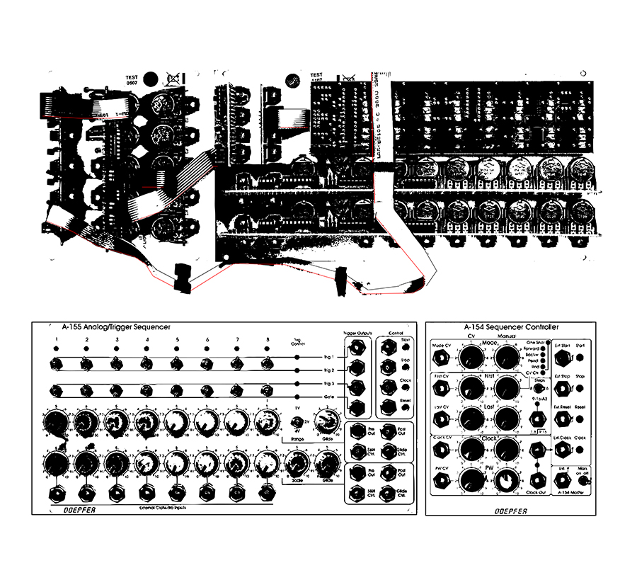
This is Doepfer’s illustration of this cable
The cable’s adventure begins at the LED board on top of the A-155, and it comes down to the first potentiometer board, and then down again to the second potentiometer board, and finally (on a stock, stand alone A-155) it extends around the little controller board and get’s plugged in in all of those places.
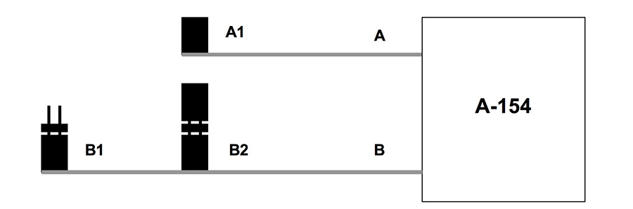
We are going to connect Cable B from the A-154 to the A-155’s potentiometer board.
So the adventure starts at the LED board, drops down to the plug on the top potentiometer board, down again to the lower potentiometer board, and then finally connects to this strange cable with a couple of jumpers in the middle of it.
These jumpers are for connecting another A-155 into this chain. If you have two and want to connect them, place A-155 number one at the end of the cable, and connect A-155 number two in the middle. If you only have one A-155 then it’s important to remember to keep the top jumper for the middle connector in the cable. It should be terminated, and thats what that dead end jumper cap does.
This cable should have come connected to the A-154, but in case it hasn’t, it extends to the left controller board at the bottom and connect to the jumper there.
Fact is, the entire module should be red stripe down. Nothing should be up, or to the right. Make sure of this. Look a few times. Sometimes with bus cables which can get wrapped around and folded up it’s easy to start getting muddled, and feel like “it’s fine” but I’ll tell you what – connect these babies the wrong way around and you’ll be enjoying the sweet, sweet sickening smell of burt IC chips before you know it. Terrible smell that takes a while to clear. I’d like to help you avoid that experience. Let’s say I’ve done it for you.
Now the inter-module power cable
This is pretty simple. Connect Cable A from the A-154 to the controller card to the left of the A-155 into jumper port ST-2.
This leaves ST-1 (the outer port) with nothing connected to it. It feels wrong but it’s exactly correct.
Finally the main power cable
This should already be connected on the A-154 but in case it isn’t, that’s located below to the cable we just connected at the bottom of the center board on the A-154. This cable just plugs into your case, or bus board. The cable should be notched so that it only goes in one way, but in case it isn’t, remember Red Stripe Down and also look and see that the red stripe destination is connected to the -12v rail on your power board.
Caveats:
If you have troubles. It’s possible that a couple of things are happening:
1. You have mid production A-155 and you’re getting grounding hassles
Here is a response from Doepfer regarding the fix for this:
I traced the GND signal and found the error: the 10 pin connector on the long trigger board which is used to connect the small board has no GND.
It’s mysterious because our technical records say that the connector is grounded. I suppose that the fault occured a few years ago when the pcb manufacturer told us that they are not able to manufacture the pcbs from the old documents any longer (the A-155 was developed nearly 20 years ago on an Atari system). But they mentioned that it’s possible to scan the old films so that they can be used in the future. I suppose that during this procedure the fault happened.
During the test of the A-155 the missing GND of the trigger sockets is not recognized as the modules are tested in combination with other modules in the same frame (i.e. with the same common GND).
The fix is very simple:
one has to connect one of the pins of the 10 pin connector of the trigger board to GND.
The GND track is just next to the pin so that a small solder blob solves the problem.
I’ll prepare a document that show the position of the required solder connection. I’m quite sure that older A-155 (manufactured directly from the Atari data) do not have
this problem.
This seems simple enough. Fire up the iron and add a little solder and the grounding problem is gone.
2. Your A-155 had been modified
There are a lot of interesting modifications to do on an A-155 Trigger Sequencer, and for some of us it’s irresistible. But you are going to have to un-modify your module if you want to use it with an A-154 Sequence Controller.
Doepfer have produced a PDF file for How To Un Mod The A-155
Score this and go over it. Compare your A-155 to the illustrations in the document. If you’re has got these, this will show you how to undo them.
That’s it. Awesome.
I hope this was helpful. I bet you could have easily figured it all out from my punk rock graphic at the top of the page, but if you actually read all this my hat is off to you my friend. You’re a good egg and I appreciate you.
Please don’t hesitate to communicate with me if you have some questions, but promise me that we’ll talk before you say “fuck it” and blow up your A-155, ok? The only dumb questions are the ones that we don’t ask, and then end up blowing up Eurorack modules.